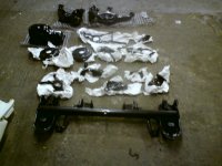
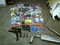
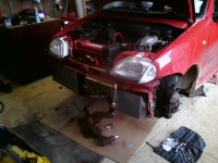
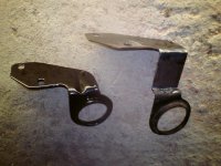
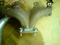
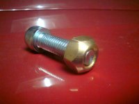
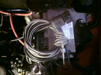
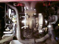
DSC00505.JPG

Seicento Monster Cento/ECU Master Thread

Introduction

Well starting this is well overdue although technically it's still just a car and a big pile of bits at the moment. It will come together quickly though as I have access to a commercial garage in the evenings and on weekends which belongs to a good friend. I'm lucky enough to have another good friend who is a self employed coded welder/fabricator and yet another good friend who owns a powder coating business. Myself, I do electronics so pretty much everything is covered. :D

I'm not going to go into minor details as most of it has been discussed before (especially the engine which was purchased from Gazzaman). However I will answer any questions and will go into detail with the DET 3 setup and installation as there are no UK guides I'm aware of for this.

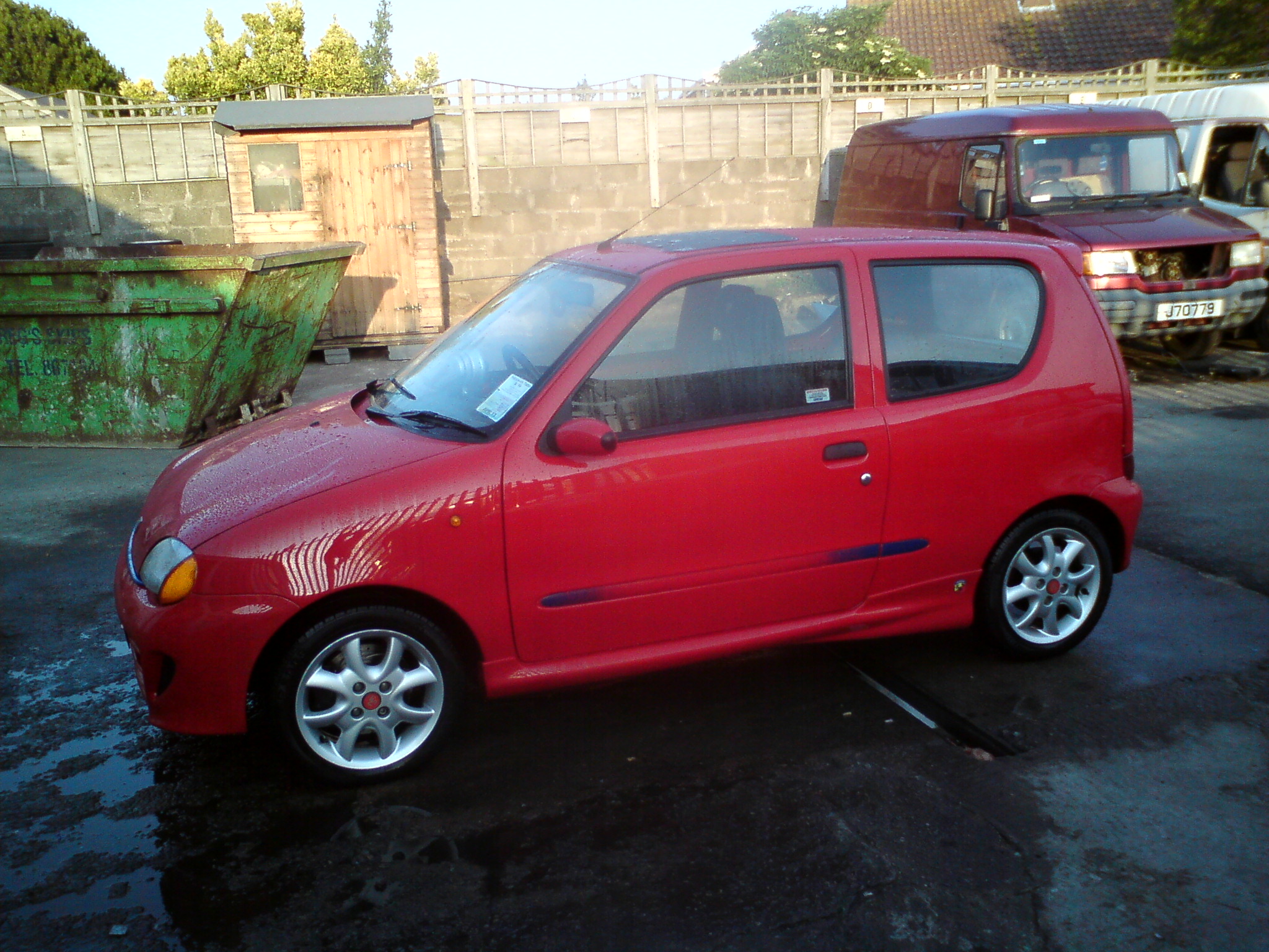
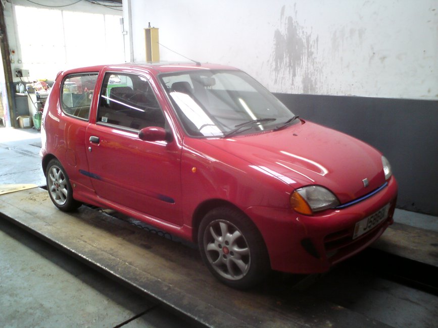
So the car:
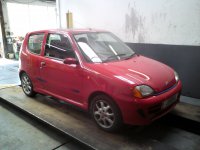
DSC00505.JPG

DSC005776.JPG


A 2000 SPI Seicento Abarth (probably manufactured late 1999) which replaces the silver Cinq (SPI Turbocharged) I have recently sold for restoration. The silver chap needed some TLC due to a bad repair from a rear collision before I purchased him. Someone made me an offer I couldn't refuse so I sold him on with the standard engine and pinched Mrs. Honeymonsters Sei after buying her a newer yellow ragtop replacement which I got a good deal on but wasn't really suitable for my project.

The planned spec is as follows, only thing I'm missing is the TB. Now Sorted (thanks Blu!)


Specification
1.2 Punto 75 Engine
Fully balanced rebuilt bottom end and crank
Ported Punto 75 MPI head with 3 angle cut valves
866 Cam with Piper vernier adjustable pulley
16v pistons/rods with skimmed block/head to adjust for suitable turbo compression
Port matched HT coated Punto 75 inlet manifold with rebuilt and tested Larger MGF VVT Injectors
Strongflex Polyurethane engine mounts
HKS mushroom filter
ECU Master ECU using fuel implant technology running MPI and solenoid boost control
Brand new GT17 Turbo with Forge racing billet actuator
Custom tigg welded GT17 exhaust manifold with high temperature coating
Forge racing billet Dump valve
Upgraded Fuel pump
Adjustable Boost referencing fuel pressure regulator
Lightened 1.2 flywheel with C&G clutch
Custom exhaust/downpipe with Magnex stainless steel silencer
Renault 5 Turbo polished and uprated Intercooler with Samco pipes and stainless bends
9 row oil cooler with Stainless braided lines
Kinugawa Stainless braided turbo water and oil feeds
Modified brand new sump tig welded for oil return and breather
Aluminum oil catch can with baffle and breather filter
Lower temperature 85c thermostat
New pumps, belts, tensioners
New leads and custom injector loom
All new seals rings and bearings
Aluminum radiator
Sparco strutbrace
Quaiffe ATB differential with new drive shafts and cv joints
Uno turbo or Punto GT Calipers (have both) with vented/grooved discs and pads
-40mm springs and upgraded shocks
Hel Braided brake lines
Monroe adjustable camber bolts (Corrected thanks Brooky :)
New tie rods and track rod ends
All suspension components including rear beam, arms etc. and front hubs, arms etc. removed and powder coated black.
Momo steering wheel, pedals and gear knob
Soundsream old skool reference series amplifier
Soundstream high end 6.5" component speakers
Image dynamics IDQ10 sub hidden in the spare wheel well.
Orion Ultra rare old school digital parametric equaliser
Audio control ESP2 spatial restoration unit
Alpine F1 Head Unit

I will just post some pictures of the bits for now and then intermittently as I fit them.

I do however need to keep this car mobile to park it back in my workshop so it will be done in big chunks.

Cheers
ah yes i think i remember talking to you about the R5GTT IC at some point now, I know of one sat in a field and borrowed the IC to offer upto my car. No way it would fit with my current arrangement of rads though.. From memory the in/outlets are massive compared to my boost pipes as well
 
Well I spent a bit of time positioning things today to see if I could find the best solutions.

I also revisited Blu's suggestion of fitting the rad on the R/H side. It does have a few clear advantages in that it allows a bit more freedom with the turbo and intercooler pipes. Oil cooler pipes could also be slightly shorter too. On second inspection my intercooler would just (damn tight) fit on the L/H side. However it also has some disadvantages unless you have the L/H drive parts. Firstly it means a rather extended run to the header tank unless you reposition it, then the existing radiator bracket can't be used as it has been handed along with the radiator for a L/H drive vehicle. Then of course the water pipes are handed wrong, but these can be quite easily modified. The radiator fan and housing sticks out over the radiator so that must also be different for the L/H drive vehicle too. Finally it would require making large holes it the bumper leg which will probably be the biggest deciding factor for me. It could be made to fit without these parts but how well is the question. I'll have one more look tomorrow, have a chat with my fabricator mate and see what we come up with. Then based on the outcome I will make a final decision.

If I stick to my original plan the radiator can be pivoted from the L/H fixing points by extending the R/H bracket (welding a section in the middle) which provides plenty of clearance to resolve any heat/pipe work issues. It will also keep everything looking tidy and factory fitting. I don't really want to swiss cheese Monsters nose with non standard holes, I have tried not to make modifications to the car through out the project which would prevent me from returning it to standard with simple replacement parts. :)

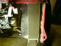
Until I pivot the rad though you can see it's quite tight:

DSC00085.JPG

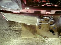
Also this metal water pipe needs to be removed extended and adjusted to suit, maybe even tomorrow with a bit of luck. (y)

DSC00087.JPG

Finally just trying to find sensible positions for things:

DSC00098.JPG

Intercooler is fine but I can't really have the oil cooler here unless I cut an opening in the bumper or lose the number plate lol. Most likely I will drop it as low as possible in this position on some brackets. I'm hoping to put the air filter above it anyway. The airfilter is the mushroom type so it ideally needs to face forward at the front of the car to collect the cold air while being unable to collect the hot air from behind it.

So much to do, whether forecast suggests it's going to be freezing cold over the weekend with arctic winds. (n)

Winter is finally here.
 
Last edited:
that metal water pipe is adpated by VA on my car, but they didn't do a good job of it tbh. Just looked through my pics and i can't really see a good but it has a bend right at the end and doesn't have the flare on end anymore either, was one of the bits i really struggled to get to not leak - but the pipes around there and the 4way branch are far to close to turbo on mine. Suggest you try temp fitting of water pipes before you decide exactly how you want to modify that pipe just to make sure nothing is too close to turbo. I need to buy some more pipe so i can rearrange it all (again).

Mine issue on mine is the expansion tank to 4way branch.
 
Yeah it's a tricky one to resolve nicely no doubt. I've seen some pretty untidy solutions while searching for pictures. I'm going to take my time, do it once do it right. I know what you mean about the pipe that goes to the expansion tank, I have no idea why they made it so crazy long in the first place. Luckilly with the intercooler having both fittings on one end I have quite a lot of space, however a slightly shorter intercooler with a few more rows to compensate would have been nice. Gaz had modified the water pipe that came already on the engine, but my turbo being so different it ended up stopping dead in the inlet. :) I have a few standards ones lying about just incase I don't get it right first time. (y)
 
it really was the only way to seal it, i need to make a new metal pipe really - i was thinking of extending a original one in the horizontal axis to bring the branch towards passenger side a bit and away from the turbo, what VA did was extend it forwards but they clearly just cut it and welded on a 90* bend on the end. This means where you need to clamp pipe on is a bend. Perhaps it would have worked if they had just cut and welded a small section into the pipe but clearly they wanted to avoid doing 2 welds rather than 1 :rolleyes: Whatever happened to doing things properly - my view of VA has gone down and down and down over the years, it would seem people agreed with me as they no longer exist lol.
 
Rad is staying on the left. After extending the bracket below (original on left) there's plenty of room for all the gubbins and heat shield. Also still clears the bumper by plenty. Just need to get it along with some other bits to Jimbo for a quick Powder Coating.

DSC00103.JPG

Just home for dinner, then back out to do some more. Gonna be a late one, good things usually happen when we do late nights. More pictures to follow. :D
 
It's a GT1749s Blu.

Well we got a few bits done, not as much as I would of liked since we spent far too much time chatting and drinking tea LOL.

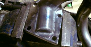
The high tensile bolts are now captive on the exahust manifold and it's nearly ready to get an 800c high temperature coating a Jimbo's place. Just need to weld on some nuts for a heat shield and decide where to put the manifold brace:

DSC00118.JPG

Also some self locking nuts have been aquired for all the manifold and turbo fixings:

DSC00114.JPG

After much jiggling it seems this would be the best place for the oil cooler (only place it actually really fits!), however it will make it 10 times harder to mount the intercooler. I might even get a smaller oil cooler to make things a bit easier. I had all the resilient mounts placed and nicely positioned for the intercooler too. :bang:

Hmm choices choices:

DSC00115.JPG


And finally that rad bracket fitted:

DSC00113.JPG

In case anyone thinks I'm fitting that tired rad I of course have a brand new one to fit with all the fan brackets etc. powder coated. I'm using the old one to line things up so it doesn't get damaged. :)

Any oil cooler mounting suggestions please post. (y)
 
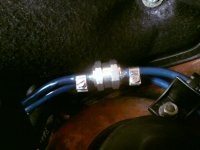
Evap system retained, shiny non-return valve fitted as per Woj's sugestion. (y)

It took a lot of colourful language and boiling hot water to get the plastic pipes over the valve! The clips do little more than look nice...

DSC00001.JPG

Need to have a good clean in the engine bay actually, that's not rust it's mud.

Bigger injectors fitted and some other bits and pieces but I haven't taken any photos yet.

Things are moving along slowly but nicely, think we might design our own 4 way pipe joiner to get a perfect run on the water pipes near the turbo.
 
Our solution to wastegate clearance while still retaining room to remove the oil filter:

DSC00007.JPG

Horrid bunch of wires for all the gauges/sensors I need to hook up and intergrate into the loom. I will spend some time making all this perfect once everything is running:

DSC00008.JPG

That's twin automotive by the way not the stuff for your bedside lamp. LOL
The grey is a screened for the knock sensor, big fella is the wideband and the stainless braided is EGT.
 
Well the good news is there is plenty of room to get the oil filter on and off. The bad news is I will have to rethink the rear bolt between the turbo and manifold as there is no room or access for the nut. Most likely I will use a time sert and fit a cap head from above. Plenty of room to access it from above the manifold. I might use a Nord Lock as thread lock would be useless at these temperatures. Also I'm going to have to be creative with the oil cooler lines unless I relocate the temp sender from the back of the sandwich plate. I could move it and refit the blank, it's not a real issue but I'd like to keep it where it is. I have a nice 90 end on the turbo suply line (block side) so that shouldn't be a problem. I still need to fit and work out a position for the actuator. The turbo came with no actuator but I was given a brand new Forge item and I have a selection of mounting brackets I can modify. Another useful thing thats happened is since the rad bracket mod is the supply line from the header tank is well clear of the turbo and down pipe. This is especially true once it's cliped to the rad so it probably won't need relocating once the heat shield is fitted. I'm hoping to get a decent amount done this evening I only got an hour on it today. It's proving difficult to pin Desy down he's always very busy and running round like a headless chicken. I can throw a weld down with a mig, just nothing like he can with a tig so it will just have to take as long as it takes.

DSC00001.JPG
 
Last edited:
Regarding the water pipes, I would still consider routing all water upwards of the turbo, you will get more space for the air pipes, you don't see that yet perhaps, but you will. Also on a Cinq/Sei you want to save every 1 deg. of water temperature, keeping the line away from the downpipe would help with that.

Other hints: I managed to live my whole turbo life without the oil-pressure gauge (although I had one almost mounted, there was some problems with electrics and I gave up), what I find really necessary though is oil temperature. So you can as well get rid of the pressure sender altogether if you want to save space.

From Todger's thread: Denis, a.k.a. TurboCinqy1250 ordered his custom sized low compression forged pistons for 8V from U.S. And payed considerable money for that. But that was back in 2006 I think. BTW, I wonder how is his car doing, I don't think he visits here so often anymore.

As a curiosity (now I am just keyboard happy drinking my before work coffee :D) I wonder why the t-jet pistons you quoted in Todger's thread have still such high compression ratio. They go from 9.8 to 9.5. For 300 and above powers I would expect less CR :confused: Anyhow, nice ashtrays :D
 
yep my water pipe goes straight across the back of the slam panel and then down to the 4 way branch, mine is still far far to close to the turbo really (although it still has never overheated) it is the cause of that illusive leak i had in the end. Close enough for the constant heating and cooling to eventually loosen a jubilee clip. With the rad on yours though the way mine is would be fine and there would be loads of clearance from the turbo. I currently got extra silicone pipe and a bit of heat shield protecting it at the moment until i have chance to take bumper off again (bit of a bugger when its your daily isn't it! I not had this problem for years, i don't like it lol)
 
Back
Top