Replacing the LEDs
Now the job of replacing the LEDs begins!
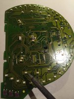
In the photo below, the soldering iron is pointing to one of the inner ring of illumination LEDs (rather than the outer ring of warning light LEDs).

Have some desolder braid handy. A damp sponge (or damp rag) helps to keep the soldering iron tip clean. You need a fine-point soldering iron of approximately 25W power - a good-quality iron, like a Goot or Weller-branded product, certainly helps. I don't think a gas soldering iron is appropriate for this job, but you might have your own favourite Portasol or something with a fine tip.
Of course, the proper way to solder SMD devices is with a syringe of solder paste and a hot air reflow/rework gun, but unless you work in the electronics industry as I used to, you probably won't have one (and I don't have one myself

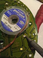
To remove the existing LEDs, press the soldering iron hard against one side for about a second as shown above, and use the tip to pry the LED off the circuit board just far enough to break the solder 'bubble'. Then desolder the other side of the LED and flick the LED away (the leg desoldered second will be badly bent, so it won't be fit for reuse). The (top quality) circuit board is robust enough to withstand this without tracks lifting, as long as your soldering iron is not overly-hot (25W, remember).
Remove excess solder from the circuit board by placing solder braid flat over the circuit board pads, then wipe with the soldering iron held on top of the braid. This might seem obvious, but you can all laugh at me: on my first day in prototype construction, I was holding the cut end of the braid end-on to the solder, I thought that was how it was used
You now need some 3253 SMD LEDs. Note these have a chamfered corner that indicates which way around that they go.
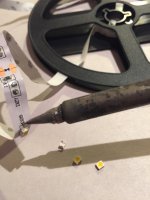
I made things a little harder by choosing to buy LEDs on a strip, as they were more readily available and cheaper than individual LEDs. This effectively makes the LEDs second-hand, as they have to be desoldered from the strip (by folding the strip and flicking the LED off with the soldering iron), then some will need to be wiped against the iron to get a flat bottom surface before placing on the circuit board.

Holding the LED in place on the circuit board (with a fingernail, or screwdriver) one side is 'tacked' into place, then the other side is soldered properly (with additional solder), and finally the tacked side is resoldered. And all the while, care is necessary not to melt the white plastic of the LED itself. The iron should only be applied for about a second at most.
Also, be careful not to melt or damage the warning light LEDs around the perimeter - the risk is obvious

Some of the LEDs are likely to be a little crooked as you see in the photo above, but they should at least be symmetrically placed on the circuit board pads. (True SMD soldering, with solder paste, hot air, and clean new parts, is a beautiful process: capillary action draws the parts into line as the solder flows onto the pads - this is why the parts on a top-quality circuit board are always perfectly aligned).
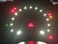
Once the LEDs are mounted, it is probably a good idea to test the bare circuit board again. I found that two of my LEDs were slightly greener than the others - overheating the LEDs is a possible cause of this - so I replaced those two again (with a 5m strip, there are a few spares

Compared to the photo at the bottom of the previous page, the colour difference between 'needles' and 'numbers' is now quite obvious - the warm white has a glow similar to traditional bulbs, which I feel is in keeping with the retro style.
I know some of you reading this will prefer cool white, blue, pink, or green - and that is entirely your choice
Continues page 5...

