I found that the standard orange colour of the speedo and rev counter numbers was hard to read at a glance. The orange was very dark and the red needles did not stand out sufficiently against the numbers. This might be more of a problem with the retro-inspired Lounge and Pop design, rather than the Sport (which has conventional numbers).

This photo shows the standard colours, though it is difficult to capture light colours with a camera - here, the LCD looks quite a lot yellower than it actually is, and therefore, the orange numbers also appear lighter than they actually are.
You will need 3253 SMD LEDs.
In g50245's guide for replacing Punto cluster LEDs, the website www.crazyleds.co.uk is mentioned. I found that guide highly inspirational, by the way - thanks g50245")
I did a search on an NZ auction site and bought two 5m reels of LED strips - with a bathroom renovation in mind - I bought both cool white and warm white, and one strip was the waterproof type, encapsulated in clear resin. The resin can be peeled off to expose the LEDs - it is like the resin that fastens CDs onto magazine covers! However, after much deliberation, I decided to use the warm white LEDs - these turned out to be on the strip without the resin.
So, once you have your LEDs, find yourself Philips number 2, Torx 10, and Torx 25 screwdrivers/bits, with a short version of the T10 and long versions of the Philips, the T10, and the T25. I use a 1/4" ratchet handle with long extension and three separate 1/4" bits.
You will also need at least two flat blade screwdrivers, fairly wide but thin blades (approx. 5mm wide), and these tools need to be clean - no oil or grease!
Start by removing two Philips screws under the steering column lower shroud. Remove the lower shroud by using your hands to pull it from the upper shroud - it is clipped at its top edge.
Then reach up beside the column stalks and remove two more Philips screws that secure the upper shroud to the stalk assembly. Lift away the upper shroud.
The instrument binnacle has two T10 screws exposed now that the steering column shroud is removed - you may need to deflect the rubber flap and turn the steering wheel/move the stalks to get clear access to undo these screws with a long screwdriver.
There is one T10 screw under the top centre of the binnacle - use a short screwdriver to remove this, then gently work the binnacle off (it is caught by the body-coloured dashboard trim panel, but it can be removed without damaging the trim.)
By this point, you have probably found a magnetic pickup tool - handy for retrieving dropped screws from the knee airbag assembly
The instrument cluster itself is held in by four Torx T25 screws - fairly large, and tight - then the cluster comes out easily to reveal a single plug connector which has a red locking lever. Press down on the detent on top of the plug, so that you can swing the lever fully out (it clicks) - then the plug comes out.
Sorry there are no photos of these steps - but this is, quite honestly, the easy part - if removing the cluster seems too difficult to accomplish without damage, it is probably best not to proceed
Continues page 2...
This photo shows the standard colours, though it is difficult to capture light colours with a camera - here, the LCD looks quite a lot yellower than it actually is, and therefore, the orange numbers also appear lighter than they actually are.
You will need 3253 SMD LEDs.
In g50245's guide for replacing Punto cluster LEDs, the website www.crazyleds.co.uk is mentioned. I found that guide highly inspirational, by the way - thanks g50245
I did a search on an NZ auction site and bought two 5m reels of LED strips - with a bathroom renovation in mind - I bought both cool white and warm white, and one strip was the waterproof type, encapsulated in clear resin. The resin can be peeled off to expose the LEDs - it is like the resin that fastens CDs onto magazine covers! However, after much deliberation, I decided to use the warm white LEDs - these turned out to be on the strip without the resin.
So, once you have your LEDs, find yourself Philips number 2, Torx 10, and Torx 25 screwdrivers/bits, with a short version of the T10 and long versions of the Philips, the T10, and the T25. I use a 1/4" ratchet handle with long extension and three separate 1/4" bits.
You will also need at least two flat blade screwdrivers, fairly wide but thin blades (approx. 5mm wide), and these tools need to be clean - no oil or grease!
Start by removing two Philips screws under the steering column lower shroud. Remove the lower shroud by using your hands to pull it from the upper shroud - it is clipped at its top edge.
Then reach up beside the column stalks and remove two more Philips screws that secure the upper shroud to the stalk assembly. Lift away the upper shroud.
The instrument binnacle has two T10 screws exposed now that the steering column shroud is removed - you may need to deflect the rubber flap and turn the steering wheel/move the stalks to get clear access to undo these screws with a long screwdriver.
There is one T10 screw under the top centre of the binnacle - use a short screwdriver to remove this, then gently work the binnacle off (it is caught by the body-coloured dashboard trim panel, but it can be removed without damaging the trim.)
By this point, you have probably found a magnetic pickup tool - handy for retrieving dropped screws from the knee airbag assembly
The instrument cluster itself is held in by four Torx T25 screws - fairly large, and tight - then the cluster comes out easily to reveal a single plug connector which has a red locking lever. Press down on the detent on top of the plug, so that you can swing the lever fully out (it clicks) - then the plug comes out.
Sorry there are no photos of these steps - but this is, quite honestly, the easy part - if removing the cluster seems too difficult to accomplish without damage, it is probably best not to proceed
Continues page 2...
Dismantling the cluster
Start by removing the foam and three Menu buttons from the front of the cluster. This is a LOT easier said than done, as the buttons (in black or ivory) are fastened onto two white fingers each, and you can only see/release one of these fingers. I found a fair amount of force was required with a flat blade screwdriver to press in the finger you can see, while twisting/pulling the button off. It would be bad if the white fingers snapped off, but they didn't for me. It doesn't matter if the spidery links between the buttons break (I broke those) - separate buttons will still work fine. This part of the job takes nearly ten minutes just to pop off three buttons, but it is definitely the hardest part of the disassembly. You might like to make a note of which button is which (a photo here would have been a good thing; sorry).
Remove all the Philips screws from the rear of the cluster. Some of these screws secure parts inside the cluster, and some secure the rear cover - but it is OK to remove all the screws together, then unclip the layers in sequence.
Pry out the securing clips and remove the front of the cluster (including the clear lens) and set it aside where dust cannot get inside it.
Pry out more securing clips and remove the rear of the cluster (i.e. the black plastic cover). Again, sorry there are no photos, but it is self-explanatory.
Now you will see a ribbon connector for the LCD. Use your fingernail to lift the black plastic clip (around the ribbon cable) on each side - then the ribbon cable will lift out - no pulling force is required if you have released the clip/clasp correctly.
Wash and dry your hands
Look for two black clips/tabs sticking through the back of the circuit board. These hold the LCD assembly in place - squeeze them to release, but also carefully pull the circular LCD housing away. It should then lift off. Don't try to release the graphic rings with the numbers yet - the needles must come off first.
If you want to change the LCD colour, now is the time to cut off its melted assembly fixings and take it apart. I considered this, and decided not to.
View attachment 151997
With the LCD removed, you can see the two concentric needles. They can be moved by hand - note their full anti-clockwise position is just below the 0 marks as shown in the photo above.
They are mounted like the hands on a clock movement - I think this is quite innovative for an instrument cluster. The rev counter needle is a tight fit on the shaft and you will need to carefully lever this upward with two screwdrivers - one on each side.
When prying, be careful of the three LEDs under the needles - these are red LEDs, which you may wish to change. Again, I considered this, and decided not to.
Don't try to pull the needle off, and don't try to make do with one screwdriver - you do not want to bend or snap anything...

With the rev counter needle removed, the rev counter numbers ring can be lifted off. There are two white clips/tabs through the circuit board for this. Note that it is illuminated by four SMD LEDs at the bottom of the transparent plastic ring (two are visible in the photo above, inside the white plastic support).
Then remove the speedo needle by lifting or prying it off - it is not as tight as the rev counter needle.
Both needles have brass counterweights. It seems to me that the instrument cluster is very well engineered given the price of the 500; plastics are good quality, the circuit board is built to the highest standard, and the chrome bezel on the LCD is an especially nice touch.
Continues page 3...
Dismantling (continued) and removing the circuit board
Remove the speedometer numbers ring by releasing two further tabs from the back of the circuit board. The warning light icons simply lift off.

After seeing the three LEDs that illuminate the needles, and the four LEDs that illuminate the rev counter numbers, it comes as quite a shock to realise that there are THIRTEEN LEDs that illuminate the speedo numbers! There are even more LEDs around the perimeter, which are the generous assortment of warning lights. I did not even consider changing these!
Note that the round circle light near 120km/h on the speedo is actually a photodiode (can't see this in the photo) - I thought it would be a speed warning for certain markets, but it is the light sensor that adjusts cluster illumination when driving during the daytime.
Unclip the circuit board from the white plastic 'chassis' of the cluster. There is a small trio of three pins that needs to be saved - this connects the LCD illumination to the circuit board.
Now you have quite an assortment of parts...

You may like to test the circuit board by plugging it into the car and switching on the headlights - I wanted to (subjectively) assess the colour and brightness of the LEDs, as seen below. Perhaps you'll agree that the orange is quite similar to the red?

Continues page 4...
Replacing the LEDs
Now the job of replacing the LEDs begins!
In the photo below, the soldering iron is pointing to one of the inner ring of illumination LEDs (rather than the outer ring of warning light LEDs).

Have some desolder braid handy. A damp sponge (or damp rag) helps to keep the soldering iron tip clean. You need a fine-point soldering iron of approximately 25W power - a good-quality iron, like a Goot or Weller-branded product, certainly helps. I don't think a gas soldering iron is appropriate for this job, but you might have your own favourite Portasol or something with a fine tip.
Of course, the proper way to solder SMD devices is with a syringe of solder paste and a hot air reflow/rework gun, but unless you work in the electronics industry as I used to, you probably won't have one (and I don't have one myself
)
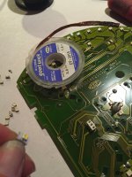
To remove the existing LEDs, press the soldering iron hard against one side for about a second as shown above, and use the tip to pry the LED off the circuit board just far enough to break the solder 'bubble'. Then desolder the other side of the LED and flick the LED away (the leg desoldered second will be badly bent, so it won't be fit for reuse). The (top quality) circuit board is robust enough to withstand this without tracks lifting, as long as your soldering iron is not overly-hot (25W, remember).
Remove excess solder from the circuit board by placing solder braid flat over the circuit board pads, then wipe with the soldering iron held on top of the braid. This might seem obvious, but you can all laugh at me: on my first day in prototype construction, I was holding the cut end of the braid end-on to the solder, I thought that was how it was used
You now need some 3253 SMD LEDs. Note these have a chamfered corner that indicates which way around that they go.
I made things a little harder by choosing to buy LEDs on a strip, as they were more readily available and cheaper than individual LEDs. This effectively makes the LEDs second-hand, as they have to be desoldered from the strip (by folding the strip and flicking the LED off with the soldering iron), then some will need to be wiped against the iron to get a flat bottom surface before placing on the circuit board.

Holding the LED in place on the circuit board (with a fingernail, or screwdriver) one side is 'tacked' into place, then the other side is soldered properly (with additional solder), and finally the tacked side is resoldered. And all the while, care is necessary not to melt the white plastic of the LED itself. The iron should only be applied for about a second at most.
Also, be careful not to melt or damage the warning light LEDs around the perimeter - the risk is obvious
Some of the LEDs are likely to be a little crooked as you see in the photo above, but they should at least be symmetrically placed on the circuit board pads. (True SMD soldering, with solder paste, hot air, and clean new parts, is a beautiful process: capillary action draws the parts into line as the solder flows onto the pads - this is why the parts on a top-quality circuit board are always perfectly aligned).
Once the LEDs are mounted, it is probably a good idea to test the bare circuit board again. I found that two of my LEDs were slightly greener than the others - overheating the LEDs is a possible cause of this - so I replaced those two again (with a 5m strip, there are a few spares
). All my LEDs worked, but I imagine that with the LEDs wired in series, it may take a few careful prods to find the single poor connection that might prevent several LEDs from illuminating.
Compared to the photo at the bottom of the previous page, the colour difference between 'needles' and 'numbers' is now quite obvious - the warm white has a glow similar to traditional bulbs, which I feel is in keeping with the retro style.
I know some of you reading this will prefer cool white, blue, pink, or green - and that is entirely your choice
Continues page 5...
Reassembly
Reassembly, as they say, is the reversal of removal... but note the following points.
Wash and dry your hands again
Turn on air conditioning if temperature is over 23C and humidity is over 80% as it is here...! You probably think I'm being silly writing this... but I've worked on many instrument clusters over the years, and there is nothing more annoying than an oily fingerprint that you don't see until weeks later, and then you see it on every trip The white plastic frame goes back on first, remembering the small assembly of three pins which is pushed through into the circuit board next (the pins are fitted in the photo below).
Then refit the warning light icon ring, and the speedometer numbers, followed by the speedometer needle. Note that the needle should be just below the zero with the mechanism turned fully anti-clockwise, as you see in the photo below.

The rev counter numbers go on next - as with the speedo numbers, make doubly sure these are fully pressed into place - the ring is only supported at the bottom (because the speedo needle has to travel around under it) - so be careful to push in the right places! It really is quite some piece of design...
The rev counter needle requires a really firm press - I suggest putting it on about a third of the way, then refit the cluster to the car and turn the ignition on - the two needles should both move up slightly and should both point to 0.
After a couple of tries, and when you are satisfied, push the needles fully home and refit the LCD housing. On the back side, lift the clasp/latch before inserting the ribbon cable, then press it down with a nice click (top-quality parts).
Give the cluster a good dusting/buffing with a microfibre cloth - especially the chrome ring, where fingerprints would look most horrid. If there are, somehow, oily marks on the matt surfaces, use nothing other than hand soap and a damp sponge, then dry with the microfibre cloth - use absolutely no other solvents (no meths, no brake cleaner), or it will end in tears - just my advice
Blow any dust out from inside the front lens - I don't recommend an air compressor, as most emit oily vapours - use a can of compressed air or a camera blower brush etc. Perhaps I should have listed all these things on the first page...
Pop the casings (front and rear) back on.
Put on the three buttons - noting that they are not symmetrical - and refit the foam.
Polish the lens with plastic polish - I use Meguiars Plast-X.
Refit the cluster to the car - perhaps with replacement felt strips on the binnacle tabs if yours have worn through or fallen off.

The total time for all this is only an hour or two and the total cost about £10... I think I've spent longer on this guide than the project itself
I didn't change the LCD colour, as I thought it was best to leave something that matched all the other illumination in the cabin - but I am now seriously tempted to change everything else to white as well
That would be the sunroof switch, radio, Sport button, fog light switch, climate control panel, window switches, Dualogic selector, USB socket, and the electric mirror controls on the driver's door.I did a number of web searches first and found g50245's guide for the Punto. Otherwise I found only one photo of a modified 500 cluster - on a Mini forum - and I can't find it again to include here, sorry!
Have fun, and please share your results