Dismantling the cluster
Start by removing the foam and three Menu buttons from the front of the cluster. This is a LOT easier said than done, as the buttons (in black or ivory) are fastened onto two white fingers each, and you can only see/release one of these fingers. I found a fair amount of force was required with a flat blade screwdriver to press in the finger you can see, while twisting/pulling the button off. It would be bad if the white fingers snapped off, but they didn't for me. It doesn't matter if the spidery links between the buttons break (I broke those) - separate buttons will still work fine. This part of the job takes nearly ten minutes just to pop off three buttons, but it is definitely the hardest part of the disassembly. You might like to make a note of which button is which (a photo here would have been a good thing; sorry).
Remove all the Philips screws from the rear of the cluster. Some of these screws secure parts inside the cluster, and some secure the rear cover - but it is OK to remove all the screws together, then unclip the layers in sequence.
Pry out the securing clips and remove the front of the cluster (including the clear lens) and set it aside where dust cannot get inside it.
Pry out more securing clips and remove the rear of the cluster (i.e. the black plastic cover). Again, sorry there are no photos, but it is self-explanatory.
Now you will see a ribbon connector for the LCD. Use your fingernail to lift the black plastic clip (around the ribbon cable) on each side - then the ribbon cable will lift out - no pulling force is required if you have released the clip/clasp correctly.
Wash and dry your hands
Look for two black clips/tabs sticking through the back of the circuit board. These hold the LCD assembly in place - squeeze them to release, but also carefully pull the circular LCD housing away. It should then lift off. Don't try to release the graphic rings with the numbers yet - the needles must come off first.
If you want to change the LCD colour, now is the time to cut off its melted assembly fixings and take it apart. I considered this, and decided not to.
View attachment 151997
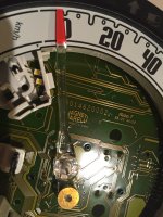
With the LCD removed, you can see the two concentric needles. They can be moved by hand - note their full anti-clockwise position is just below the 0 marks as shown in the photo above.
They are mounted like the hands on a clock movement - I think this is quite innovative for an instrument cluster. The rev counter needle is a tight fit on the shaft and you will need to carefully lever this upward with two screwdrivers - one on each side.
When prying, be careful of the three LEDs under the needles - these are red LEDs, which you may wish to change. Again, I considered this, and decided not to.
Don't try to pull the needle off, and don't try to make do with one screwdriver - you do not want to bend or snap anything...

With the rev counter needle removed, the rev counter numbers ring can be lifted off. There are two white clips/tabs through the circuit board for this. Note that it is illuminated by four SMD LEDs at the bottom of the transparent plastic ring (two are visible in the photo above, inside the white plastic support).
Then remove the speedo needle by lifting or prying it off - it is not as tight as the rev counter needle.
Both needles have brass counterweights. It seems to me that the instrument cluster is very well engineered given the price of the 500; plastics are good quality, the circuit board is built to the highest standard, and the chrome bezel on the LCD is an especially nice touch.
Continues page 3...

