Dismantling (continued) and removing the circuit board
Remove the speedometer numbers ring by releasing two further tabs from the back of the circuit board. The warning light icons simply lift off.

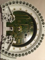
After seeing the three LEDs that illuminate the needles, and the four LEDs that illuminate the rev counter numbers, it comes as quite a shock to realise that there are THIRTEEN LEDs that illuminate the speedo numbers! There are even more LEDs around the perimeter, which are the generous assortment of warning lights. I did not even consider changing these!
Note that the round circle light near 120km/h on the speedo is actually a photodiode (can't see this in the photo) - I thought it would be a speed warning for certain markets, but it is the light sensor that adjusts cluster illumination when driving during the daytime.
Unclip the circuit board from the white plastic 'chassis' of the cluster. There is a small trio of three pins that needs to be saved - this connects the LCD illumination to the circuit board.
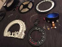
Now you have quite an assortment of parts...

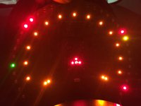
You may like to test the circuit board by plugging it into the car and switching on the headlights - I wanted to (subjectively) assess the colour and brightness of the LEDs, as seen below. Perhaps you'll agree that the orange is quite similar to the red?

Continues page 4...

