Technical Death Rattle!!!!!!

Currently reading:
Technical Death Rattle!!!!!!

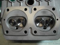
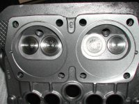
Well, it's been a while since a bit of good news has come my way with my engine problems, but, after sitting down with my engineer and making a plan for the rebuild I can safely say that the full reassembly is now a week away (ish) (y)(y) After having the crankshaft reground at both the main and big end bearings by one step oversize we did a sample reassembly using new bearings to accurately measure the deck height. Using a base support plate of apparently 1.00 mm (actually 1.25mm) the deck height came out at -0.51mm added to this was the Head gasket of 0.50mm thickness giving us a squish area of 1.01 mm :eek: This is toward the high end of the recommended range (range being 0.9144mm to 1.143mm or 36 to 45 thou in old money:rolleyes:) There is some room to manoeuvre on these figures but it is largely dependant on cam and combustion chamber size. As my Cam is 35/75-75/35 (290) and my chamber sizes are 34.2cc and 35.7cc I was looking at 10:1 C/R for a reliable fast road set up.:devil: It was found that due to a squish step that was cut into my 34.2cc head (see pic) this made it difficult to fit a gasket without disturbing the squish action as the piston came up to TDC so the only reason is this head has been altered to run without a gasket. But if we removed the gasket the C/R would reach over 11:1 and cause the squish band performance to go below the minimum figure of 0.9144mm - Back to square 1 (n)(n) My other head - later Panda 30, still has the gas ring and the original chamber profile, but has been skimmed slightly to give 35.7cc capacity. If we ran with the 1.25mm base plate and used an 81.5mm bore gasket of 0.5mm thickness this would give around 9.8:1 C/R with an acceptable squish area from the head capacity. So result!! (y)(y)(y) As part of the balancing exercise we are checking the piston and conrod weights to equalise them prior to balancing the crank. I intend to include the rear pulley and flywheel with clutch pressure plate too. I'll get back with balancing news when I have it.

Ian. DSCN2497.JPG
DSCN2500.JPG
 
My data sheet states an inner liner squish of 1 - 1.2mm. There is no statement regarding cylinder head squish. CR of 11 - 11.5 : 1 and the use of high octane fuel.
Are you lightening the flywheel?
Spec says 4kg
 
Last edited:
My data sheet states an inner liner squish of 1 - 1.2mm. There is no statement regarding cylinder head squish. CR of 11 - 11.5 : 1 and the use of high octane fuel.
Are you lightening the flywheel?
Spec says 4kg

Hi Andrew, thanks for the info (y) Yes I am going to use a lightened flywheel, my present one is actually reduced to 4.8kg and that will suit me fine as I'm not looking for anything much lighter. I seem to be collecting parts for another engine now!! :devil::devil: maybe something a little more wild in the future :eek::eek:

Ian.
 
Wild seems ok to me!
Hoping for 55 - 60 hp at flywheel
What are you hoping for?
My MOT has been delayed by building works at home and a vety busy work schedule...still looking forward to flames on the over run........
 
Last edited:
Everything is back from the engineer and ready for the final balancing to be carried out. (y)(y) I had ordered a "high quality" main bearing set from AG (Item number: 01032/A0,2 Standard crankshaft main bearing set, minus allowance 0.2, High Quality:) and was very pleased to note that they were of Italian make and of Phosphor bronze material. :devil: So they should be able to take the higher loads associated with Tuning. One thing I had not expected was a difference in the Piston/Rod assembly weight(s) (n)(n) my engineer found that the forged pistons were nearly the same (within 0.5gm) but the shock was the rod end weight with number 1 being 9gm heavier :eek::eek::eek:
according to my man this would have placed extra stress on the big end bearing and the main bearing!!!! Anyway, they all weigh the same now and I have the total weight for the balance factor. I'll get back when the balancing is complete.

Ian.
 
Greetings, now on with the VERY careful rebuild and while the question of crankshaft end-float has been noted in this thread previously I have also noted that my engine came apart without a Head Bearing Spring or Front Crankshaft Sealing Ring :confused::confused::confused: Question to the good and great on here - is it required?? and how do I accurately measure, and if necessary, adjust the end-float?? Many thanks in advance (y)

Ian.
 
Last edited:
Ian, to the best of my knowledge there is no way that you can adjust the crankshaft end-float--it is or it isn't! It can be checked without the timing-chain cover in place, as long as the pulley, oil-thrower etc are all in place with the crank-nut tightened up to the correct torque. The end play, measured between the flywheel-end bearing face and the crank-shaft shoulder should be .0118" to .0173" (0,30mm to 0,44mm). This is quite strange, because in the 'pukka' book of words, the picture clearly shows the feeler inserted at the TIMING-CHAIN end of the crank-shaft!? If it would help you, I will put a copy of this page into the post to you.
The crank-shaft seal (flywheel end) should have a spring in it--the spring helps hold the seal lips against the surface it is sealing. There should also be a spring ring behind the crank sprocket, as well as 2 (Fiat's description) 'plates. Again, do you want me to send you a picture of this? --it is from the 'factory' parts catalogue. What do mean by "head bearing spring"?:confused::)

Thanks Tom - appreciated. The crankshaft seal is a new item and does have the spring you mention, the 'head bearing spring' is the description from the AG site, I think it would be better described as a 'front crankshaft sealing ring' or 'spring ring' you quote in front of the spacer and oil seal (I'll get two on order pronto)
Can you please send me both of the pictures you speak of as it will help me now and in the future. (y)(y)(y)

Ian.
 
Ian Bleeding Knuckles. Apart from the timing chain sprocket, I have these bits on the bench so I have had a good look at them. Assuming that the sprocket "floats" on the crankshaft, the amount of end-float achieved is dependent on the precision in manufacture of the main-bearing thrust-face and of the timing-sprocket thickness. The nosing of the oil-slinger pulley is what bears on that sprocket and subsequently onto the thrust washers. The internal machining of the slinger-pulley acts as a stop because once it is tightened it bears on the crankshaft end; so I suspect that a non-original pulley could also affect the end-float. But if you had to increase or reduce the end-float I think that internal machining of that pulley or the addition of shims inside it would be a better way to achieve perfection.
As far as I know there is one thrust disc which has a piston-ring compressed into a circumferential slot and a plain washer which bears onto that, shown in this image:

LIS_0268 by Peter Thompson, on Flickr

I guess the idea is that rotational forces combined with lubricant-oil will push the ringed disc slightly away from the white-metal thrust surface and that the piston ring pressure will maintain that position. So that small amount of clearance is needed to allow this and to avoid metal to metal contact.

Logically, the most accurate measurement would be taken at the pulley end as this is where the interface between the crankshaft and the thrust bearing is located...ie. the two surfaces as photographed:

LIS_0273 by Peter Thompson, on Flickr

LIS_0271 by Peter Thompson, on Flickr
 
Last edited:
Peter and Tom, thanks for your input gents - a great help, I have just received the spring rings and will get on with the assembly (y)(y) It's a pity that Christmas slows things down (the mail) as I'm waiting for some new serrated spring washers for the countersunk screws on the rear main bearing carrier!! :bang: I note your points regarding "adjustment" Peter, but I wonder how it would have been done in the day - just change the spacer and disc and measure again hoping for between 0.30 to 0.44mm ?????? :eek::eek::eek:

Ian.
 
I note your points regarding "adjustment" Peter, but I wonder how it would have been done in the day -

On original assembly there would have been a choice of many components which could be used, each with tiny differences in manufacturing tolerances. They would have been able to substitute if there was a significant mis-fit.
It would also be possible to machine the thrust face of the white-metal more or less as required.
I would assemble the crankshaft without the conical washers and measure the clearance, just to get that out of the way. It saves crushing the serrations if it does need to be dismantled again.

Have just done a 'trial assembly' as you recommend Peter, and lo and behold I have a Crankshaft End-Float of between a slack 0.10 to a tight 0.15mm, so bearing mind Tom's book of words quotes between 0.30 to 0.44mm I reckon that even with new parts, the assembly will bed in nicely during the running in process (y)(y)(y)

Ian.
 
I reckon that even with new parts, the assembly will bed in nicely during the running in process (y)(y)(y)

I think you're right Ian, and if anyone wants to contradict you I expect that we will learn more from them about this elusive subject. I note that I asked the same direct question as you quite some time ago and had no takers then.:)

I haven't seen any write-ups of 500 or 126 engine rebuilds (other than yours) where this subject got a mention.
 
Last edited:
I think you're right Ian, and if anyone wants to contradict you I expect that we will learn more from them about this elusive subject. I note that I asked the same direct question as you quite some time ago and had no takers then.:)

I haven't seen any write-ups of 500 or 126 engine rebuilds (other than yours) where this subject got a mention.

Yes Peter we shall see, sometimes the little items get missed in the middle of a big job (n) My next fiddly task is the accurate timing of the camshaft :(
I have a lightweight camshaft timing sprocket (similar to item No 5545 on the Ritz Handels site) that came off of my engine some time ago with elongated bolt holes, so I'll set to with my trusty DTi and degree disc - more to follow (y)(y)
Ian.
 
Ian;
When, by using your degree disc, DTi and elongated cam-sprocket holes, you have got the cam timing spot on, remove the cam WITH THE SPROCKET STILL SECURED TO THE CAMSHAFT. Look at the back of the flange on the cam (where the sprocket sits) and you will find a 5th (small) hole. Drill through this hole AND THE SPROCKET. Mark the cam location on the sprocket, remove the cam-drive sprocket from the camshaft and then tap a thread in the little hole in the cam-shaft flange. Enlarge the (5th) hole in the sprocket, just big enough to get the appropriate bolt through that hole. Re-affix the sprocket to the cam-shaft AND the 5th little bolt. This bolt takes very little load, but will ensure that the cam timing stays as set---you do not have to then rely entirely on the tightness of the 4 main securing screws in elongated slots. (y):)
 
Have just done a 'trial assembly' as you recommend Peter, and lo and behold I have a Crankshaft End-Float of between a slack 0.10 to a tight 0.15mm, so bearing mind Tom's book of words quotes between 0.30 to 0.44mm I reckon that even with new parts, the assembly will bed in nicely during the running in process (y)(y)(y)

Ian.

Ian, I'd suggest you double-check your crankshaft end-float. Have you tried tapping the crank backwards and forwards with a mallet to settle everything into place and then levering it in both directions when taking your measurements? Pulling and pushing it by hand might not be enough to give you an accurate reading.

Now, I reckon I'm not smarter than the Engineers at the factory, so if they they say 0.3 - 0.44mm, that's what I'd want to end up with. Remember why you need this clearance - to allow for expansion (Aluminium alloy bearing versus steel crankshaft) plus 2 x spaces (one each side of the bearing) for oil films to exist. Too little clearance as the alloy bearing expands may leave no room for an oil film and result in metal-to-metal contact.

I don't think that these parts will 'bed-in' nor are they designed to, in the sense of the clearance increasing from 0.10/0.15mm to the specified 0.30/0.44mm in use.

Peter's pic of a crankshaft above shows, imho,metal tearing on the thrust surface. I'd want to clean that up before re-use.

I'm not trying to 'rain-on your parade' when you're eager to make progress in re-assembling your engine, just trying to help. I'd hate for your new engine to give you problems...

AL.
 
Peter's pic of a crankshaft above shows, imho,metal tearing on the thrust surface. I'd want to clean that up before re-use.

.

:D:D:D

That crank and bearing is definitely "in-the-raw":D, having been sitting on the bench for twelve months and being sprayed with grease as a preservative. I'm planning to assemble it with new bearings and the pistons in the near future so will check the condition and end-float then.

There are so many measurements like this, which you never hear of people checking on this little engine. I'm sure that getting them all right adds up to creating a smooth and reliable engine; it's just that sometimes you have to draw a line and make a compromise or you never get anywhere.:):bang:

Thanks to Al and Peter, I'm just back in from the workshop (shed):rolleyes:
and can report that even with the application of some 'hammer' the measurements remain the same:confused::confused: Now, a question for the good and great on here, what does one do?? I appreciate that the missing clearance is some 0.15 to 0.17mm to give me the Minimum quoted in Tom's book of words, and that the apparent lack of said clearance is down to either the fitting of the new bearing into the carrier or the thickness of the spacer on the other side of the assembly - correct or not??? So, can I simply use some emery paper and a flat surface and reduce the thickness of the spacer by the magic 0.15mm??? Answers on a post card please to ............. otherwise I will need to get a nod from a professional engine man from the 500 clan (y)(y)

Ian.
 
You could try rubbing down the front main bearing thrust-face on oiled wet and dry on a sheet of glass, as sometimes recommended for the cylinder head. Maybe they are deliberately made slightly oversized?

Yes Peter, that would be my next option, but I must say it would be a very reluctant choice as the main bearing set was plenty pennies :eek::eek: The spacer was measured at 3.05mm thickness and I am unsure if other sizes are available??? I really do wonder what the factory would have done.... anyone have an idea???? - I'll ask around anyway (y)(y)

Ian.
 
Back
Top