1677188756264.png

600 (Classic) 1960 600 EV conversion

Introduction

Hello all... I am new to this forum and I am in the midst of converting my 1960 600 to electric. I have converted one other classic car to electric 3 years ago (1964 Corvair) and it has been wonderful. The corvair is a convertible and we drive it daily all summer (in the pacific NW). I want a classic ev conversion that will also allow us to drive year round. Thats where the 600 comes in. We are all small car fans in this fam, and this little guy is just too damn cute. I have been working on the car for about 6 months at this point, and now that I have worked out most of the big-ticket items, i thought it was time to share it with y'all.

First off, i know there is alot of controversy about converting old cars to electric. Everyone will have their own opinion on if its the right thing to do or not. I can tell you, for me, its totally the right thing to do, for many reasons. With that... lets get to it.

My goals:
- 120 miles of range
- 75mph top speed
- Safer than it was
- Looks stock
- Can still haul 4 people
- Use it all year

The major parts i plan to use:
- Hyper9 144V AC motor and controller (@ 120hp/180ft-lbs this motor is WAY too big for this car. its a long story, but its what i ended up with)
- (6) Tesla model s battery modules
- Orion2 BMS
- 2.5kW charger
- Early beetle transmission (why? well, they have loads of aftermarket support and they have been used in countless EV conversion with the motor i plan to use. out little transmissions are just too unique and unknown, in comparison).

The major things i needed to figure out right away:
- where can i stash all these batteries?
- will the motor fit in the back
- how will i manage the HVAC? (since i want this to be usable year round)
- how will i upgrade the brakes?

This first couple of posts will get after the batteries and the motor fitment.

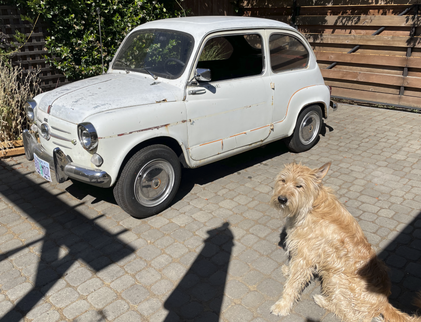
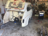
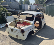
here is the car as bought:
1677188756264.png


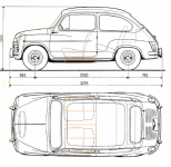
I bought the car in august 2022. Clearly my dog Marty is super excited about all the time i will be spending working on it, rather than going for walks. The car had spent alot of its life at the coast, so the rust is not ideal. This is my first body work project, so I dont expect it to be a show car. When i was planning this conversion, i carefully measured up where and how i could fit the (6) battery modules in the car. Most of the old Fiat conversion (mostly 500s in the UK it seems) use (3) tesla modules and place them under the bonnet and boot. The floors in this car need replacing, so i worked on a plan to place the batteries under the seats, just like modern EVs. It will keep the center of gravity low and give me space for other stuff up front and have storage in the back. Here is some cad exploration: You can see the battery module outline in orange.
1677188973641.png


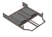
So, according to my rough CAD, i could fit 4 modules across the bottom of the car, and then one additional module under each front seat, between the seat rails. It will lower the floor of the car about 1.25in and raise the seat about 1in. The new seat rails will be on either side of modules 5 and 6. Like this:
1677189217454.png


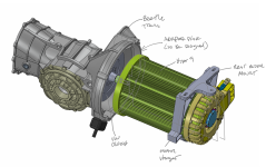
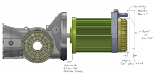
This will give me a voltage range of about 108-151V. The motor and motor controller i chose can support 90-180V, so its just right. Speaking of the motor, i made sure it will fit between the transmission and rear bumper panel. I also found a CAD model of a beetle transmission so i can work on new mounts and adapter plates. Here is how it is coming together:
1677189800457.png

Note the clearance to the back of the car and how i plan to use the existing motor mount to hang the back of the assembly from. I will also be working on getting the standard transmission mounts adapted to the car, but i am less concerned with that, at this point:
1677189865602.png


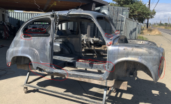
So, now that it doesnt seem totally CRAZY to fit all of this stuff in the car, I got to work taking the car apart, preparing it for a metal dip. Here are some progress pics of the tear down (note the car was originally red):
1677190398627.png


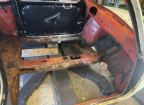
here you can see how rotted the floors were:
1677190464594.png


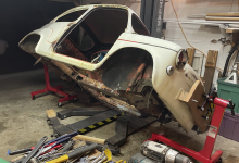
I also built a makeshift rotisserie out of harbor freight engine stands. I cant flip the car over completely, but i can rotate it 90deg either direction.
1677190555284.png


After completely stripping everything off of the car, it was time to haul it to the metal dip shop (in Eugene OR, totally awesome place):
1677190641567.png


When the car came back from the dip shop, i was heartbroken. i had a big decision to make... it was bad. Really bad. Should i scrap this car? I considered it. I would have to replace nearly everything. Even the doors were completely unsalvageable.
1677190955199.png


I had to source replacement doors. The only early (suicide) door i found on Ebay was 1000$. If i had to spent 2k$ on doors, this project was sunk. I decided that if i couldnt find reasonably priced doors, i was going to scrap it. Then i discovered Chris Obert down in Santa Cruz CA. He had 16 doors for me to choose from and sells them for 150$ ea. He was kind enough to take a video of each door, reviewing their health and let me choose. it was awesome. the project was back on!
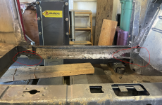
After deciding to proceed with this project, i got to work cutting and welding and cutting and welding. Getting the battery tray integrated into the car was tricky. It needed to hold the batteries but also be structural. I had to also replace the rocker planels, so i cut them out and got to work integrating the battery tray into the old bones of this car. Here are some progress pics:

here you can see how rotted the rockers are:
1677192464949.png


I cut out inner portion of the rocker and replaced it with some 0.120 steel to begin hanging the battery tray from:
1677192624900.png


Then i cut out the shape of the rocker, matching the rockers that were on the car. Maybe most of you car buffs know this stuff, but i am just learning. Its amazing how much planning needs to be done to preserve the position of the original body panels. I tried to keep things in the same spot, so the door had a chance of working again. More on that later. Here is how it looks cut out:
1677192756618.png


now that those were in, i was comfortable cutting out the center tunnel, which i am pretty sure was keeping the car together (i know the rockers werent doing anything!). and i started getting the angle iron in its place. Here you can see the first test fit of one of the tesla modules:
1677192866165.png

And here is what it looks like with all (4) modules across the floor... pretty bad ass, if you ask me!
1677192929390.png


and here is with a module place under the passenger seat with the new seat rails:
1677193044453.png


and finally (modules removed) with both seats and new rails in place. The seats are in the furthest back position. I moved them back because i have long legs and we wont have many passengers back there. They do move up quite a bit for that occasion, however.
1677193097645.png


you might notice the cable coming up from the seat rail. That is a cable system i sorted out allowing the moving of the seat front to back. here is a close up. I am not sure i like it enough to keep it, but its a good start:
1677193224868.png


Most folks may be aware that these types of batteries need liquid thermal management. I have thought about that while laying this out. Here is a sketch on how i plan to do that. The feed and return lines will run through the sheetmetal under the back seat and be directed to a pump and peltier device located under rear seat, drivers side. Like this:
1677193706700.png

and as i added angle iron to rebuild the structure of the car and hold the batteries and people, i welded in nuts in places i think i might need them... like for seat belt anchors.

Now that the battery tray was installed, i started working on replacing the rocker panels and rear wheel arches. This is all typical body work stuff, so i wont belabor it. It may not be pretty, but so it goes. Its my first attempt and this stuff. The copper colored paint is weld through primer:
1677193985156.png

and with a new rocker (though i had to use a later model year part since the older parts arent available. it made it harder, sadly) and a new rear fender panel:
1677194073542.png


i did that to both side of the car and moderate success. Now, it was time to start working on the front end of the car. More to come.
 

Attachments

  • 1677192584949.png
    1677192584949.png
    6.6 MB · Views: 111
The front of the car will house the HVAC, charger, DC-DC converter and likely most of the wiring. I dont plan to have a spare tire up there any longer. I plan to have most of the storage in the back, where the engine used to be. I also wanted to upgrade the brakes. I have parts to do a front disk conversion. I am also uncomfortable with single piston master cylinders. So, now i need to place the air conditioner, heater, duct work, new brake master cylinders, 12V battery and other electronics all under the hood. Before i got to cutting the front of the car up completely, i began placing the new brake master cylinder. I am not maintaining the clutch in this car. It will have a manual transmission, but i will leave it in 2nd or 3rd gear all the time. More on that later. What this means for now is i have more room for the pedals. I can move the brake over to the left so my bigger feet can access it more comfortably. My foot would hit both the brake and clutch before. I ordered up a dual master wilwood set with my best guess at a pedal ratio and cylinder bores. The nice thing about this setup is that you can order a variety of cylinder bores, so if i guessed completely wrong, i can change one or both out for bigger or smaller. If the force is too high, i can put a smaller master cylinder bore, at the expense of pedal travel. It will be a balancing act. It also has a bias bar, which will be important to tune the front/rear ratio after its all done. I know its possible cuz i saw something similar on madFiat's 58 little rocket, so that gave me some hope. Here are some pics on how i setup the pedal position and brackets to hold it all.
I temporarily mounted the seat and the steering wheel and got to work on pedal placement. I started with a small hole in the firewall, and made it bigger as i zeroed in on the right spot.
1677216865584.png


the position of a brake pedal with respect to the gas pedal isnt something i have given much thought, in the past. But now, its completely up to me, so i suddenly cared alot about it. I went around to my other cars and friends cars and got a sense of the relationship between the two and ended up with something like this:
1677216980858.png

I was happy with that placement, so i got to building the brackets for the master cylinder:
1677217032883.png

and now that the brakes are installed, its was time to see how i could get the A/C unit in the car. Picking an A/C system was a challenge. With the space we have in these cars, getting a traditional A/C conversion kit folks normally put in old cars wasnt an option. Plus, they are pretty expensive. i found this outfit called rigidhvac online (https://www.rigidhvac.com/store/products/micro-dc-aircon-dv3830e-ac-r134a) and they make mini DC A/C units. They sell several that run on 12V, 24V and 48V. I chose the 48V version because it has slightly higher cooling capacity but 3x the blower volume of the lower voltage systems. This gives me the best chance of having some reasonable cooling on the hottest of days, but it now means i need an additional dc to dc converter. Now i have to convert the pack high voltage (up to 150V) to 48V. I found a place that sells those, so i ordered one. Not cheap. Here is a test fit with the A/C unit and master cylinder.
1677217525859.png


So now i know this stuff can fit together. its time to replace the fenders and nose on this little car. cutting it all up:
1677217603872.png


here you can see some structure i am adding for the A/C and other stuff.
1677217672298.png


Here is a front shot of the A/C and brake mount:
1677217757945.png


now its time to get fenders and the nose back on. It was important that i test fit the hood to make sure it could close properly before i welded things together completely. its starting to look like a car again:
1677217834299.png


You may have noticed that the center Fiat emblem on this car was replaced with a 3rd headlight sometime during its life. I sorta like it and want to keep it... and I plan to add the charge port behind that 3rd headlight. This also needs to jive well with the A/C unit. It fits, by some miracle, exactly between the heat exchanger and the blower box after i gently moved some copper lines out of the way. So lucky:

1677218034381.png


How do i move the headlight? i tried to design a simple hinge, but it didnt work out. I had to use a 4-bar linkage instead. Here is how that turned out:
1677218108334.png

And open with the charge cable inserted:
1677218157871.png


I am pleased with how it turned out. Here is what the mechanism looks like with the headlight removed. I have access to a 3D printer and was able to print all these linkage and carrier parts:
1677218232044.png


I intend on building the charge status LEDs into this 3rd headlight, so while the car is charging, the headlight will glow red/yellow/green depending on the charge of the battery.

So, in summary, here is a pic of the fenders and nose fully welded in place with the A/C, brake, charger and some EV components placed where i think they will end up:
1677218379174.png


next up, i will be working on the HVAC ducting. I have thought more about how the ducting than anything else on this build so far. It really helps me appreciate how awesome modern car's HVAC is... those engineers are really clever. I plan to use the little starter/choke lever thing to control the air. One lever will move the air from the windshield to the passengers. The other will select fresh or recirculated air. I will have to add a switch for the blower fan, another to turn on the A/C and a third for the heater. Speaking of the heater, my plan is to use an element from a portable hair dryer.
 
Brilliant write up and report! Also can I add, your work for a I believe first timer is well thought out and executed!
I'm delighted you are doing this to a car that needs restoration over chopping up a perfectly good car, there are quite a few lovely examples online that are being cut to bits to allow the conversion.

I looked into this but the cost over in Europe was extortionate, the range just wasnt there and the recharge time would kill me. I looked at it in that, the cost would buy a lot of fuel, the range of my 500 and 850 on a full tank is ideal and when they run low two minutes at a pump and €30 and we're off again.

Well done again, keep us posted! While I'm not sold on the whole electric car thing I do like to see creative and well executed work!

One thing that does bother me and I hope you never have to deal with it, battery fire. When they go up they go up rapidly, I think this is why a lot of the kits available store them up front, allows you time to stop and escape, will there be some kind of containment......they're very close to your ass/other important bits and I suspect bbq'd genitals is a concern......
Also, weight, very well constructed but with all that weight and reinforcement will your range suffer more then you have figured?
 
Thanks very much for the kind words. Now that i caught everyone up on the project the posts will be less often.

As for the risk of BBQ'd buns, i do plan to cover the batteries. First with a layer of FR4 as puncture protection, then i will form some ABS as a cover for it all. That will buy me a little bit of time if a "thermal run-a-way" event happens, at a the cell level. Its unlikely, but a good point to bring up. I will be carefully monitoring the battery temps and pumping coolant through them when needed. I also plan to have several fuses around the pack to prevent shorting and run-a-way current through the entire battery. I will also be adding a intertial switch (for any accidents, where the impact will disconnect the batteries).

According to the CAD model of the additional structure i am adding to the car, it calculates about 70lbs of additional metal for the battery tray. I think that is worth it and will still keep the car well below 2000lbs. I expect to add a total of 245lbs to the car after the conversion.

Speaking of weight... i did some math to determine the additional weight the car will bear, but also the new distribution. When i pulled the engine, i weighed it and it came in at 210lbs. I estimate the gas to be about 30lbs when full. Then i will add 330lbs of battery and a 120lb electric motor. Ignoring all the odds and ends, that puts the total weight gain at about 245bs.

The new weight distribution took more work to figure out. Digging back to my static classes in college, i was able to solve these equations:
1677606235135.png


the bottom line: i will add at least 245lbs. The old weight distribution (according to the interwebs) was 38% front, 62% rear. The new weight distribution will be 46% front and 54% rear.

I dont think it will effect my range much. I am more worried about rolling resistance of the tires and drag from the poor aerodynamics at this point. We will see!
 
While we are on the subject of math, i thought i would share the drive train plan and resulting speeds. I mentioned above that I will be using a Beetle transmission... specifically i am using one with a 4.375 final drive. It will have the reinforced spider gears set (4 instead of 2) for the extra hp. The gear ratios are:
3.78 1st
2.06 2nd
1.32 3rd
0.89 4th
Final drive is 4.375

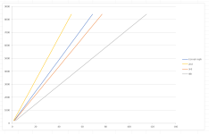
I chose this version on purpose; there are many options. The Hyper9 is an AC motor, so it can spin over 8000 rpm with reasonable efficiency. This means I can leave the car in one gear, if i wanted, and never shift. This is exactly what i did with my Corvair EV conversion. It has a 3spd manual, and i leave it in 2nd gear... all the time. To go in reverse, i just spin the motor the other way. I compared my gear ratios to the Corvair because i know exactly what the Corvair feels like. It is not a rocket off the line, but fun from 10-50mph, then it tapers off to a stop speed of 70mph. I want the fiat to feel peppier around town, but also cruise on the freeway at a lower motor RPM. This means for the 600, i will actually have a "high" and a "low" speed. I wont shift when moving (if you'll remember i deleted the clutch). I didnt have room for it at my feet and i dont have room for the flywheel and clutch between the motor and transmission. While at rest, i can select high or low (3rd or 2nd). I may also use 4th gear, for a longer trip at high speeds, but we will see about that. It might be too tall for accelerating from a stand still. The speed vs RPM curves look like this:
1677642942766.png


The actual speeds and RPM look like this...
1677642999110.png

top speed in 2nd will be 60mph, 3rd will be 95mph, and 4th will be 140mph(!!). 4800 RPM is the peak power for this motor. Around town, 2nd will be fine. 3rd looks great for most freeway driving. 4th would only be useful for higher sustained speeds. We will see if its useful.

For reference, the motor efficiency curve from the Netgain website looks like this:
1677642079108.png

you can see that the efficiency is really good the entire RPM range this graph covers. This is why DC motors are becoming less popular, and more folks are using AC motors. AC motors are alot more expensive, though. There is always a flip side. If i used a DC motor, i would have kept the clutch because they are not efficient across a wide RPM band. It would require shifting. DC motors are also hard to drive backwards, so i would need to put it in teh reverse gear.

The 600 should be much peppier. 2nd gear will be slightly shorter and the car will weigh nearly 1000lbs less. I cant wait!
 

Attachments

  • 1677641743679.png
    1677641743679.png
    78.4 KB · Views: 93
  • 1677641922534.png
    1677641922534.png
    139.4 KB · Views: 107
Last edited:
I don't know how many folks reading this have done body work on a car, but i am really enjoying it though it takes so so much time. In the USA we have a company called Eastwood that seems to have everything you need to do body work and fantastic tutorial videos. I grew up in the Midwest (Detroit) and i am still paranoid about cars rusting, even though i haven't lived there for 30yrs. As a result, i am thinking a lot about rust prevention on this 600. Afterall, i don't want this thing to rust in 5 years after all the work i am pouring into it. While the car is opened up, its an ideal time to spray some nasty chemicals in the nooks and crannies in an attempt to at least slow the rust. Yesterday, i used this product in the rockers and rear quarter panels:
1677775595570.png


You can hook that hose up to the spray can and insert it into frame tubes (or rockers, in my case). I used two cans on the car yesterday. I left the ends of the rocker panels open so i could get the tube in there and drenched it. I know it got in there cuz the paint was dripping between my spot-welded seams. It was very satisfying. I then plan to weld in the finishing plates in the wheel wells to cap the rocker off. I will drill a drainage hole in the rocker somewhere, but i will hold off until after i see how the car sits. It had a bit of a squat when i bought it, so if i end up maintaining that i will drill the hold towards the back so any water that does get in can drip out. In the meantime, i am continuing to repair damaged panels like these in the rear wheel arches:
1677775813401.png


I will spray some rubberized goopy stuff (like bed liner) in the wheel wells to prevent rust, nicks and for sound damping. This will hide my welds and any panel incongruency. But before all of that, I plan to try Eastwoods roll on epoxy primer. It is described as the best stuff to put on raw metal. It seals it, is very hard and creates a great bond. After epoxy priming the entire car (except the stuff i cant reach, hence the frame paint above), i will get to work on any bondo required for the small dents i couldn't pound out successfully or did so poorly and cover up my crummy welds. Then, i will take it to a paint shop for a sealer and paint. Thats my plan anyway. I still have plenty of body work before that happens, so that plan may change. Next up: the rear deck lid and window. This is going to be a very tricky; it's a mess and i cannot buy replacement panels. i will have to fabricate it. I am very worried about maintaining a good surface for the window seal. I have new window gaskets coming from oldtimer-shop (it's a great part resource, but takes a while for shipping to the USA) so i can test fit before too much welding:
1677776316818.png
look at those holes!
 
Go onto ebay.it, have a search for the username "minibike53".
He has a second hand complete roof for a 600 up there, he maybe able to cut the rest from the car and do a deal for you on it. It could save you so much time on fabrication.

Also, not sure if you get waxoil in the US, it's a brilliant product to just pour/spray inside the sills/rockers. Drilling drain holes may just entice more moisture.
I don't know how many folks reading this have done body work on a car, but i am really enjoying it though it takes so so much time. In the USA we have a company called Eastwood that seems to have everything you need to do body work and fantastic tutorial videos. I grew up in the Midwest (Detroit) and i am still paranoid about cars rusting, even though i haven't lived there for 30yrs. As a result, i am thinking a lot about rust prevention on this 600. Afterall, i don't want this thing to rust in 5 years after all the work i am pouring into it. While the car is opened up, its an ideal time to spray some nasty chemicals in the nooks and crannies in an attempt to at least slow the rust. Yesterday, i used this product in the rockers and rear quarter panels:
View attachment 419552

You can hook that hose up to the spray can and insert it into frame tubes (or rockers, in my case). I used two cans on the car yesterday. I left the ends of the rocker panels open so i could get the tube in there and drenched it. I know it got in there cuz the paint was dripping between my spot-welded seams. It was very satisfying. I then plan to weld in the finishing plates in the wheel wells to cap the rocker off. I will drill a drainage hole in the rocker somewhere, but i will hold off until after i see how the car sits. It had a bit of a squat when i bought it, so if i end up maintaining that i will drill the hold towards the back so any water that does get in can drip out. In the meantime, i am continuing to repair damaged panels like these in the rear wheel arches:
View attachment 419553

I will spray some rubberized goopy stuff (like bed liner) in the wheel wells to prevent rust, nicks and for sound damping. This will hide my welds and any panel incongruency. But before all of that, I plan to try Eastwoods roll on epoxy primer. It is described as the best stuff to put on raw metal. It seals it, is very hard and creates a great bond. After epoxy priming the entire car (except the stuff i cant reach, hence the frame paint above), i will get to work on any bondo required for the small dents i couldn't pound out successfully or did so poorly and cover up my crummy welds. Then, i will take it to a paint shop for a sealer and paint. Thats my plan anyway. I still have plenty of body work before that happens, so that plan may change. Next up: the rear deck lid and window. This is going to be a very tricky; it's a mess and i cannot buy replacement panels. i will have to fabricate it. I am very worried about maintaining a good surface for the window seal. I have new window gaskets coming from oldtimer-shop (it's a great part resource, but takes a while for shipping to the USA) so i can test fit before too much welding:
View attachment 419554 look at those holes!
 
Go onto ebay.it, have a search for the username "minibike53".
He has a second hand complete roof for a 600 up there, he maybe able to cut the rest from the car and do a deal for you on it. It could save you so much time on fabrication.

Also, not sure if you get waxoil in the US, it's a brilliant product to just pour/spray inside the sills/rockers. Drilling drain holes may just entice more moisture.
Thanks @FR85 for the tips. I looked around in ebay without any luck. Ill keep my eye out while i wait for the window gasket parts to arrive.

It does look like we can get waxoil in the US. I already committed to the Eastwood stuff, but for anyone in the USA wondering, it seems we have options! https://www.waxoyl-usa.com/ As for the drain holes... thats a good thought. If i added one, i would likely but seal it with a rubber drain hole plug. Maybe i will reconsider the entire idea.
Also, not sure if you get them or are familiar with the history but Fiat were built in Spain under the Seat brand so you could try eBay.es under Seat 600 or also in Serbia under Zastava, they were built as the 770 over there.

You don't just have to stick with Fiat....
 
Howdy folks. Between welding in new or repairing body panels, i have been working on adding more structure to the back 1/3 of the car. So far, i have added lots of structure to the middle and front the car for the batteries. I connected the battery tray with the front spring perches, which look strong and healthy. I wanted to add a roll bar and some rear stays, so i thought it should be good to tie it all together.

The car is getting heavier for sure, but most of the weight is being added to the mid section of the car. Like this:
1678237783624.png


I added lots of support to the middle and front of the car, so i feel good about that. I am working on the back 1/3 now. Here is the rough plan:
1678237850408.png


I am now learning about tube bending. So far, I have only ruined half of my material, so i will need to get more. But now that i have the hang of it, its turning out ok. Here is a test fit of half of the roll bar and stay system i worked on over the weekend:
1678237928571.png


Next up, i will get more material and try to duplicate that half and get it welded in. I hope my window parts show up soon.

Also, I no longer have the same fire wall needs, so i am removing the panel behind the back seat. This will enlarge our storage space, at the expense of torsional rigidity. I will be working more on that and plan to make the roll bar system do that work for me as well. I am excited by the amount of space back there.
1678238131751.png
 
I made some progress on the rear window and roll bar this week. I am pleased with how the roll bar turned out. I had to build the hoop in halves, then weld the two halves together. I did this because I needed to make sure the rear seat back would still fold down and not interfere with the hoop at all, and bending both sides would have introduced too much error. It worked out well (though tight) in the end. I gotta say, getting the rear stays bent up correctly in the right spot was tricky. Its all welded in now. Here is how that all turned out:
1679076511761.png


Now it's time to tackle that rear window. My window seals arrived so I could finally get started. I struggled a bit with how best to recreate it. There wasn't a lot of material left for me to reference. I came up with a plan though, that is working out well so far. Its not done, but I thought i would share the process I used. First, I placed a shop lamp inside the car, shining out the back window. Then I placed a paper template over the rear window opening. This allowed me to trace any metal that was still present. I did this all the way across the bottom. Like this:
1679078070163.png

Now, I made the rather large assumption that the car is symmetric and I folded the paper template in half. I was able to use the traced lines on the left side to fill in missing info on the right side, and vice versa. By piecing the good bits together like that, I was able to nearly recreate the curvature. The rest I interpolated the best i could. Like this:
1679076922731.png

Then I placed the template on the car and checked with the rear window and seal:
1679076973529.png

It looks pretty good. I compared the gaps around the top and sides and my template, and they all seem about the same. I have no idea how precise this all needs to be. I will just keep checking as I go along, I suppose. Worst case, I may have to add some Bondo to tighten up the fit. So, now that I have the best template I can make, I cut out the rotted bits of the outer sheet metal. I left the inner portion intact to help verify my new assembly didn't warp while welding. I will remove them when I get it all welded up.
1679077189779.png

In the pic above with the roll bar in place, you can see the lower valence (?) under the window tacked into place (I took that pic after some of these). That also gave me some guidance on the curvature of the new sheet metal. Here is where it stands now and I plan to get it welded in over the weekend.
1679077351218.png

It's a lot of the same... cut out the rot, make a new panel, weld it in. I am looking forward to getting this thing primered!

Question for the group: Can someone post a close up pic of their rear window from the inside? I have no idea how the headliner interacts with the rear window surround sheet metal. Or how much the window seal covers things up. I will have to rebuild that part too, and I would love some inspiration. There don't seem to be any pics online of that part of the side of the car... at least I could not find any worthwhile. Thanks in advance!
 

Attachments

  • 1679076791004.png
    1679076791004.png
    4.8 MB · Views: 96
I did get the external rear window frame finished up, but progress has been slow with work travel and spring break. I welded in the lower half of the rear window and replaced a general portion of the upper as well.
1681416537274.png

next up, i will be rebuilding the inside of the rear window and drip ledge across the top of the boot lid. I kept the old one as a template, so its "just" a matter of making another. I am picking up material for that, along with material needed to finish out the trunk area and a large sheet to be the belly pan under the batteries and foot wells.

time will tell how much work i am creating for my future self. These new panels are not perfect, so i will have to clean it up with block sanding and bondo. We will see.
 
while traveling for work (not sleeping on account of jet lag), I did more planning for a few things.
1. how to interface with VW transmission, both mounting and shifting
2. interior hvac, shifting and direction controls.
3. get some HVAC duct work done
4. parking brake

All of this stuff wont be installed for a while, and will likely get refined, but I like to start thinking about these things ahead of time so my mind can be munching on it in the background. Its just how my mind does it best work.

VW interface: i ordered a full transmission hanger setup offered by EMPI from a beetle part supplier out on the west coast. I am keeping the rubber mounts to keep NVH to a minimum. I ordered one of these: https://www.jbugs.com/product/9543.html and i hope to integrate it something like this:
1681417434479.png


I also found all the shifter parts for a Beetle way easier than replacement parts for the 600 shifter. Plus, the VWs is way simpler. In general, it will be better for service and replacment parts in the future. My 600 shifter was a worn out mess. The ball joint was toast:
1681417760144.png


So, i ordered a shifter kit form rock auto and the shift bar, bushings and such to convert my entire shift linkage to VW. i was fitting it last night, i think its going to be great. In fact, i should work well with the HVAC and direction control scheme i have in my mind. It will look something like this:
1681417921977.png

The "L" will be 2nd gear and the "H" will be 3rd. I plan to have three buttons. One for each: fan, heat and a/c. I will wire it so the A/C and Heat will not turn on unless the fan is on. The thing above is the repurposed choke and starter lever and i plan to have that toggle hvac output and input. I will have two vents to aim at the occupants, along with an adorable little clock that came with the car. The smaller circles will be a USB charger and the finger pump for the wiper fluid. Like this:
1681418103486.png

To feed the vents/defroster is a rather crude duct system i put together with parts found all over cyberspace and cobbled together. Like i mentioned above, the heater will be a hair drier element. Here is what that looks like, and will be plumbed to the output of the A/C unit in the pics above:
1681418296853.png


The ducting will have a diverter in it. I am sure there is a better way to design something like this, but i am struggling with something more compact that doesnt require a bunch of fab work. I just cut up some aluminum and put it on a pivot. The theory is like this:
1681418380450.png


The diverter looks like this in real life (looking through the end):
1681418481540.png

And the entire structure in the car looks like this, and its HUGE:
1681418524213.png

maybe between now and when i get to installing it, i will come up with something more streamlined. I figure most of it will be hidden by that clock and vent plate, but its hard to visualize it complete just yet.


and finally, the parking brake. This is a tricky one. As all you 600 owners probably know, the parking brake is integrated into the transmission, not the rear brakes... specifically on that little black drum hanging off the front, not unlike a big RV. This presents a problem for me. I have been noodling on it, and I have come up with a plan. Believe it or not, I plan to use the clutch as the parking brake. The clutch actuator in the VW transmission is a simple spring loaded lever, and i can use that simple lever to push some stuff into the friction material on the clutch. I have room for a couple of rectangular tubes in the bell housing that will act as a "caliper" but will not have friction material on it. The cad for this looks like this:
1681419471158.png

exciting stuff!
 
Love this, the bodywork looks great.
I did a little research into an ev conversion on my 850t but bottled proceeding with it.
I simply don't know enough to risk it, that and the range anxiety hit before the idea even left the page!

Interesting idea for the parking brake, I hope it's as simple as the drawings make it appear.
 
G
while traveling for work (not sleeping on account of jet lag), I did more planning for a few things.
1. how to interface with VW transmission, both mounting and shifting
2. interior hvac, shifting and direction controls.
3. get some HVAC duct work done
4. parking brake

All of this stuff wont be installed for a while, and will likely get refined, but I like to start thinking about these things ahead of time so my mind can be munching on it in the background. Its just how my mind does it best work.

VW interface: i ordered a full transmission hanger setup offered by EMPI from a beetle part supplier out on the west coast. I am keeping the rubber mounts to keep NVH to a minimum. I ordered one of these: https://www.jbugs.com/product/9543.html and i hope to integrate it something like this:
View attachment 421364

I also found all the shifter parts for a Beetle way easier than replacement parts for the 600 shifter. Plus, the VWs is way simpler. In general, it will be better for service and replacment parts in the future. My 600 shifter was a worn out mess. The ball joint was toast:
View attachment 421365

So, i ordered a shifter kit form rock auto and the shift bar, bushings and such to convert my entire shift linkage to VW. i was fitting it last night, i think its going to be great. In fact, i should work well with the HVAC and direction control scheme i have in my mind. It will look something like this:
View attachment 421366
The "L" will be 2nd gear and the "H" will be 3rd. I plan to have three buttons. One for each: fan, heat and a/c. I will wire it so the A/C and Heat will not turn on unless the fan is on. The thing above is the repurposed choke and starter lever and i plan to have that toggle hvac output and input. I will have two vents to aim at the occupants, along with an adorable little clock that came with the car. The smaller circles will be a USB charger and the finger pump for the wiper fluid. Like this:
View attachment 421368
To feed the vents/defroster is a rather crude duct system i put together with parts found all over cyberspace and cobbled together. Like i mentioned above, the heater will be a hair drier element. Here is what that looks like, and will be plumbed to the output of the A/C unit in the pics above:
View attachment 421369

The ducting will have a diverter in it. I am sure there is a better way to design something like this, but i am struggling with something more compact that doesnt require a bunch of fab work. I just cut up some aluminum and put it on a pivot. The theory is like this:
View attachment 421371

The diverter looks like this in real life (looking through the end):
View attachment 421372
And the entire structure in the car looks like this, and its HUGE:
View attachment 421373
maybe between now and when i get to installing it, i will come up with something more streamlined. I figure most of it will be hidden by that clock and vent plate, but its hard to visualize it complete just yet.


and finally, the parking brake. This is a tricky one. As all you 600 owners probably know, the parking brake is integrated into the transmission, not the rear brakes... specifically on that little black drum hanging off the front, not unlike a big RV. This presents a problem for me. I have been noodling on it, and I have come up with a plan. Believe it or not, I plan to use the clutch as the parking brake. The clutch actuator in the VW transmission is a simple spring loaded lever, and i can use that simple lever to push some stuff into the friction material on the clutch. I have room for a couple of rectangular tubes in the bell housing that will act as a "caliper" but will not have friction material on it. The cad for this looks like this:
View attachment 421374
exciting stuff!
Great write up with very interesting research and photos . Good luck with the project and please keep the post updated . Look foreward to reading more .
How about a solar panel on the roof ? 😋
 
G

Great write up with very interesting research and photos . Good luck with the project and please keep the post updated . Look foreward to reading more .
How about a solar panel on the roof ? 😋
Thanks very much! I actually thought about solar panels for the roof as well but ran into two problems… 1. My quick search didn’t come up with any panels that would bend gracefully in two dimensions to follow that dome roof. 2. My charger (which I already bought) does not accept DC so it would have to hack in another system to make use of the solar.

Bottom line: I love the idea, but for someone else’s project!
 
Love this, the bodywork looks great.
I did a little research into an ev conversion on my 850t but bottled proceeding with it.
I simply don't know enough to risk it, that and the range anxiety hit before the idea even left the page!

Interesting idea for the parking brake, I hope it's as simple as the drawings make it appear.
Yes, range anxiety is a real thing. I guess it all depends on how you plan to use it... but even then, it can really get ya. Some of the work I have to do is configuring the car so the range is consistent and predictable. Right now on my Corvair, the gauge can say i have 1/4 of a "tank" left, then it plummets in 10 miles. I will be working to make that more linear as well.

Keep an eye on the tech and maybe soon you can dive in! I swear I see a new article about groundbreaking battery stuff daily.
 
Back
Top