1677188756264.png

600 (Classic) 1960 600 EV conversion

Introduction

Hello all... I am new to this forum and I am in the midst of converting my 1960 600 to electric. I have converted one other classic car to electric 3 years ago (1964 Corvair) and it has been wonderful. The corvair is a convertible and we drive it daily all summer (in the pacific NW). I want a classic ev conversion that will also allow us to drive year round. Thats where the 600 comes in. We are all small car fans in this fam, and this little guy is just too damn cute. I have been working on the car for about 6 months at this point, and now that I have worked out most of the big-ticket items, i thought it was time to share it with y'all.

First off, i know there is alot of controversy about converting old cars to electric. Everyone will have their own opinion on if its the right thing to do or not. I can tell you, for me, its totally the right thing to do, for many reasons. With that... lets get to it.

My goals:
- 120 miles of range
- 75mph top speed
- Safer than it was
- Looks stock
- Can still haul 4 people
- Use it all year

The major parts i plan to use:
- Hyper9 144V AC motor and controller (@ 120hp/180ft-lbs this motor is WAY too big for this car. its a long story, but its what i ended up with)
- (6) Tesla model s battery modules
- Orion2 BMS
- 2.5kW charger
- Early beetle transmission (why? well, they have loads of aftermarket support and they have been used in countless EV conversion with the motor i plan to use. out little transmissions are just too unique and unknown, in comparison).

The major things i needed to figure out right away:
- where can i stash all these batteries?
- will the motor fit in the back
- how will i manage the HVAC? (since i want this to be usable year round)
- how will i upgrade the brakes?

This first couple of posts will get after the batteries and the motor fitment.

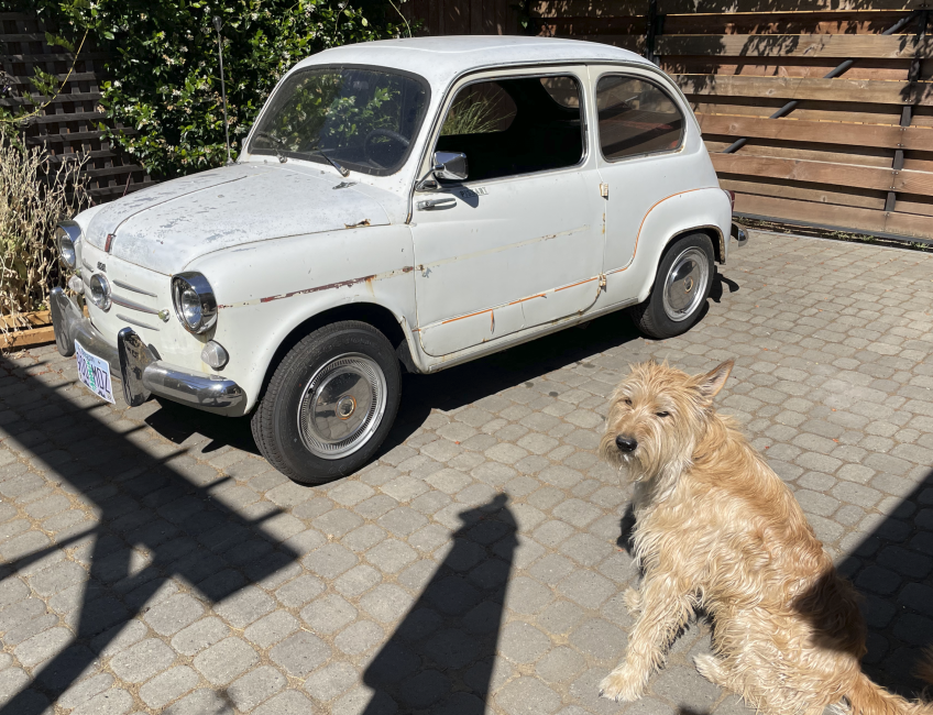
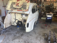
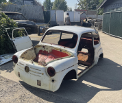
here is the car as bought:
1677188756264.png


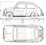
I bought the car in august 2022. Clearly my dog Marty is super excited about all the time i will be spending working on it, rather than going for walks. The car had spent alot of its life at the coast, so the rust is not ideal. This is my first body work project, so I dont expect it to be a show car. When i was planning this conversion, i carefully measured up where and how i could fit the (6) battery modules in the car. Most of the old Fiat conversion (mostly 500s in the UK it seems) use (3) tesla modules and place them under the bonnet and boot. The floors in this car need replacing, so i worked on a plan to place the batteries under the seats, just like modern EVs. It will keep the center of gravity low and give me space for other stuff up front and have storage in the back. Here is some cad exploration: You can see the battery module outline in orange.
1677188973641.png


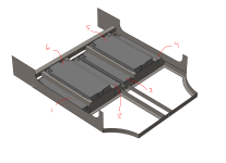
So, according to my rough CAD, i could fit 4 modules across the bottom of the car, and then one additional module under each front seat, between the seat rails. It will lower the floor of the car about 1.25in and raise the seat about 1in. The new seat rails will be on either side of modules 5 and 6. Like this:
1677189217454.png


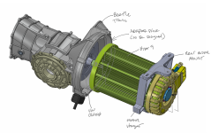
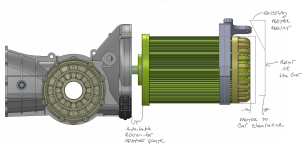
This will give me a voltage range of about 108-151V. The motor and motor controller i chose can support 90-180V, so its just right. Speaking of the motor, i made sure it will fit between the transmission and rear bumper panel. I also found a CAD model of a beetle transmission so i can work on new mounts and adapter plates. Here is how it is coming together:
1677189800457.png

Note the clearance to the back of the car and how i plan to use the existing motor mount to hang the back of the assembly from. I will also be working on getting the standard transmission mounts adapted to the car, but i am less concerned with that, at this point:
1677189865602.png


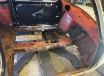
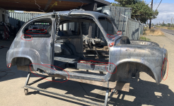
So, now that it doesnt seem totally CRAZY to fit all of this stuff in the car, I got to work taking the car apart, preparing it for a metal dip. Here are some progress pics of the tear down (note the car was originally red):
1677190398627.png


here you can see how rotted the floors were:
1677190464594.png


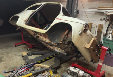
I also built a makeshift rotisserie out of harbor freight engine stands. I cant flip the car over completely, but i can rotate it 90deg either direction.
1677190555284.png


After completely stripping everything off of the car, it was time to haul it to the metal dip shop (in Eugene OR, totally awesome place):
1677190641567.png


When the car came back from the dip shop, i was heartbroken. i had a big decision to make... it was bad. Really bad. Should i scrap this car? I considered it. I would have to replace nearly everything. Even the doors were completely unsalvageable.
1677190955199.png


I had to source replacement doors. The only early (suicide) door i found on Ebay was 1000$. If i had to spent 2k$ on doors, this project was sunk. I decided that if i couldnt find reasonably priced doors, i was going to scrap it. Then i discovered Chris Obert down in Santa Cruz CA. He had 16 doors for me to choose from and sells them for 150$ ea. He was kind enough to take a video of each door, reviewing their health and let me choose. it was awesome. the project was back on!
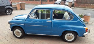
Hey everyone... Since I am deep into the body filler stage, its time to start thinking seriously about the color. I have been pretty obsessed with Fiat 419 (blu turchese) since that color has been on most of the inspiration builds I found (and thanks to this forum, I learned what the paint code is, thank you!) Like this beaut:
1694450353980.png

However, our household is also a big fan of avocado, so we are considering green. Here is the inspiration pic for that color:
1694450422375.png

I have been ordering paint samples from this spot: https://www.automotivetouchup.com/ They sell aerosol cans for about 25$USD, so its a great way to test on larger panels. I ordered a variety of Fiat blue's and the avocado. Here is the test "plaque":
1694450533221.png

It turns out that I actually dont like blu turchese (419) as much as I thought. I am actually partial to fiat 413. So, the leading candidates for the car are 413 and 374. I have the original rusty hood, so I painted each color on half:
1694450675725.png

In the end, the green is just too risky for us. Plus, we have already decided on an interior color and the panels and seat material have already been ordered and received. I chose the interior color 406:
1694450751082.png

and when placing a sample of the interior on the blue, it looks lovely. So, we have decided on blue! It feels like a very common color for these old fiats, but I have to remind myself that there very few of them around, so the chances of seeing another blue one is actually low. Time will tell!
1694450875159.png


the interior sample looks much lighter than I was expecting. I have been assured several times that I received the correct color, but it is lighter than I had hoped. So it goes.

I also ordered seat belts to match from a great seatbelt source in the US: https://www.seatbeltsplus.com/
The color "tan" is a great match. I got two sets of 3pt belts for the front and lap belts for the back:
1694451046411.png


Now back into the garage for me for MORE sanding.
 
hello everyone... I am a month into body filler and its taking a looooong time. I do feel like I am getting the hang of it, but I dont think I will ever get to a perfect finish. I am contemplating paying a shop to do the final primer, sand and paint, rather than just paint like I had planned. We will see. The process I am using to get straight body panels is as follows: After epoxy I apply something called a "guide coat" which is a sanding friendly black spray paint. Its job is to reveal the high and low points on a panel. Here are pics of a door I am working on:

As it started, you can see the dents and low spots marked with a sharpie:
1695235563651.png


Then I sprayed it with the guide coat:
1695235596867.png

Then it gets block sanded. I use 120grit. You can see the low spots still have guide coat in them, including some that I did not notice before. The guide coat and epoxy get sanded off the high spots:
1695235727664.png

I tap the high spots down with a body hammer, then clean and apply body filler. Here is what that looks like:
1695235808458.png

Then I sand all of that and repeat the process until the guide coat comes off consistently across the entire surface. This goes for the entire car. The rear quarter panel looks like this at the moment:
1695235919487.png

You might notice the inside of the wheel-well is black. The entire underside of the car is done. It was painted with Black chassis paint and the wheel-wells got a rubberized coating.

The next steps are to finish this up, apply another 2 coats of epoxy, and some urethane primer. Then I put on suspension/wheels/steering and haul it to the paint shop.
 
The fiat is headed for paint tomorrow. I am very excited! To get ready for paint, I have to get the wheels on, which means the suspension and things. A few posts ago I mentioned concern about the noisy front leaf spring. So.... I ordered an independent front suspension kit from a shop in Argentina. It seems hot rodding 600s is particularly popular in Argentina. Here is the shop: Collino They have all sorts of parts and some great videos. Translated subtitles are amazing.

The front suspension seems very nice and bolted right up. I am a bit nervous about the spherical end links being harsh, but I also have so much tire sidewall on the car, I suspect it will soften things up for me. I am also concerned the spring rate will be too high, but we will just have to try it and see. Here it is bolted up (note: i had to get some spacers to slide over the leaf spring mounting bolts at my local hardware store):
1696536991773.png

1696537016036.png

I still plan to convert it to disk brakes, but I am waiting on a few other parts, so I will make that swap later. I also cleaned up and installed the rear suspension. I decided to upgrade the half shafts to handle the power. I ordered this setup from Collino as well. I will have a driveshaft shop graft the new CV joint to the VW transmission interface when the time comes. In order to fit the bigger 128 bearing (that comes with the kit) and CV joint, the trailing arm needed some modifications. First, the hub hole needed to be opened up a few mm and I was able to do that with a grinder and various cutting bits and sanding bobs. Second, the channel the axle passes through needed to be widened to make room for the CV boot and clamp. I did that with my floor jack (it was precarious!), and just used a body hammer to add some room. Like this:
1696537441953.png

1696537515422.png

Here with the CV joint ( i have tape on it to keep it clean):
1696537587012.png

Speaking of the tires and the massive side wall, the tires that came with the car are pretty big. They are 145R13. The new front suspension has an aggressive offset. Between the tire size and the offset, I feel the tire is very close to rubbing the fender. The disk brake conversion may also affect the offset, so I will keep an eye on that. I would say there is 10-15mm of clearance to the front of the fender.
1696537763587.png

Now the car is ready to roll onto the trailer for the trip to the paint shop. Its on the ground for the first time in over a year. Exciting!
1696537853029.png
 
While the car is at the paint shop, I made some progress on the gauge cluster. I am spending a fair bit of time on it... afterall, I will be looking at it all the time. The gauge cluster that came in the car had been painted black, and I want it almond. I also needed to update the speedometer and adapt the fuel gauge for my EV application.

First up, the speedometer: The previous owner swapped out the number plate for an Italian one, so the numbers were in kph, but the gauge said mph, but neither were accurate. When I ran the gauge at "45mph", the gauge actually read something else, even after correcting for kph. Needless to say, it was a hodgepodge of parts and needed sorting. So, I found an old jolly gauge on ebay that was in mph and started the adventure of combining these two gauge pods to make one good one. This also provided an additional fuel gauge, which I need, but more on that later.

Originally i tried to recreate the digits of an mph gauge with some vinyl numbers (the original painted numbers had turned to powder and just blew away when I opened up the gauge... really funny stuff). And, although they turned out nice, it just didn't work with the dial. Here you can see the lines on the dial just don't line up with the numbers, despite it saying "M.P.H." at the bottom. Weird.
1698081626145.png


The extra cluster arrived and was in poor shape as well, but the numbers matched the dial and the digits didnt turn to dust when I opened it up. Good news! So I ran it backwards for a few days, with a small DC motor coupled to an old speedo cable, to reset the odometer and got to refinishing the housings in a nice almond color.
Here is my setup to work on the odometer:
1698081989043.png

the housings came out nice. The original gauge housing from my car came with this nice chrome bezel around the speedo, so I concentrated on that one, but have the other as a backup.
1698082065821.png


Onto the fuel gauge: I plan to use the fuel gauge to tell me the battery pack level, or "state of charge" (SOC). In order to do that, I need to graft a micro-RC car servo motor into the fuel gauge assembly. I plan to do the same on the "water" side of the gauge and have another working dial there as well. I plan to use this dial to indicate the amount of current being used by the car. It should be an "mpg" gauge of sorts. I cadded up a new bracket for the fuel gauge and printed them for both sides. The guts of the original fuel gauges are so clever. The tug-o-war of the coils on the needle, and varying one's strength with a simple resistor in the fuel tank is rad and makes me smile... anyhow, the guts:
1698082563912.png

And they came together very nicely:
1698082286698.png

I stole the needs out of the two fuel gauges, drilled them out and painted them. The servo motor fits so nicely in the volume available.
1698082372416.png

Next up was to program an arduino to control the needle position. The battery manager i use will have a 0-5V output based on the battery SOC; 0V is empty and 5V is full. So, I will program the arduino to position the needle based on the voltage provided by the battery manager. It is simpler than it sounds. Here I am learning the exact servo angles for "full" and "empty" on each gauge:
1698082667447.png


And finally... the backlighting. I wanted to update the backlighting in the gauge. I am a big fan of amber gauges, so I sourced some amber LED strips and attached a ring around the metal housing of the gauge. It has a sticky back, so I just stuck it down to the frame after cleaning:
1698082824790.png

And here is how it looks all buttoned up.
1698082877184.png
I can adjust the brightness with a simple potentiometer, and it uses less than 100mA!

I also plan to reuse the warning lights. The warning light on the fuel side of the gauge will come on when the cooling pump for the batteries comes on. It won't mean there is a problem, but I like to know when the batteries are warm enough that they need some cooling. The warning light on the water side of the gauge will indicate when the current out of the pack is being limited. My battery manager will limit the amount of current allowed to be pulled out for a variety of reasons... its too hot or too cold, or the SOC is too low. I have found that the current limit is the best way to know when to head to a charger ASAP. The generator and oil light will be my turn signals. I eliminated the signal light on the dash to keep it as clean as possible.
1698083392143.png
 
I have read about a similar project at outdoorbits. They show a lot of useful tips on planning, finding, and purchasing necessary items, as well as assembling each component
 
You've got my admiration mate, I've just done my doors and front wings and sanding flat then painting with cans was challenging to say the least. I didn't want it pristine as I wanted to match the rest of the car and it came out ok.
Love the colour you chose and personally like the light tan as think it looks classy.
Good luck with the project, out of interest any idea what you think the finished project will cost or do you not want to think about it?
Thanks very much, @stocky. Its been a haul. The car is scheduled to be back from paint tomorrow. I am excited but nervous. When I dropped the car off at the paint shop, Cody (the paint shop owner, who is totally awesome and is exactly kind of guy I like to work with) asked me if I was going to do another project like this. I winced and said "no way". He laughed and said "ah... the sting hasn't worn off yet. Give it time." I thought that was wise, especially since I already find myself looking through 80s cars on craigslist that my 15yr old son and I can work on together.

These next few months should be alot of fun. I will find out what I messed up, planned poorly for, and just forgot. I already know of a few holes I will need to drill for things that didn't occur to me until recently. I wonder what else I didn't think of :unsure:

As for cost... I am keeping decent track and I plan to share that info. When I am done with most of the purchasing, I will sum it up the best I can. I can tell you now though.... its NOT cheap. This is an expensive hobby (both time and money) to say the least. I am spending money fixing up a car that really should have been crushed, so much of what I have spent is not required for the EV conversion. Stay tuned.
Ive concentrated on the interior on mine as it was poor, seats door cards, seat belts, the outside is going to stay lived in as it was a one family car before me, plus dont need to worry about it as much. Considering a good t cut and a coat of clearcoat to just protect from our weather but not made mind up yet.
Looking forward to the photos.
Shame theres not more 600s on here, I've had a few 500s but I find them just too small.
 
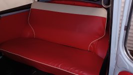
@stocky you did a great job with your interior... especially the seats (I studied the pics on the sunroof thread). I have been working on the upholstery for my seats and it's been a bear. I scrapped the bottom of the rear seat to make room for electronics, and I needed to change the outline to clear the roll bar anyway. So, its taking some trickery to get the cover to look good with the new shape:
1699554697995.png

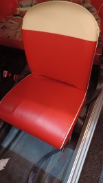
I have also been working on the front seats. When I took my front seats apart, it didnt look like there was much left that is considered "stock", so I didnt have a template to work with. I ordered new foams and covers. The rubber supports on the bottom were in good shape, so I resused them. There was no support for the back, however. When I placed the foam on the frame and sat on the seat, I could feel the metal frame with my upper back. That made me think there is supposed to be some support under the foam. So... I cut up a tractor trailer tube (that we use to float rivers, so it will need replacing in the spring) to make huge rubber bands to add support the backs. Like this:
1699555273957.png

I also reinforced the bottom bands. It felt like a good thing to do. I can cut them out without having to take the seat cushion apart if they prove to be too stiff. If you look closely, you will see I added some wire pieces to the frame to keep the back bands from sliding up and down. The foam keeps the wire in place. And I added seat heaters while i was in there:
1699555413091.png

The bottom cover was simple enough to get installed, though I dont know what I did wrong about the side skirts... they have so much extra material and flop around. I am not sure how to correct that. The backs took ALOT of work to get the covers to slide over the foam. I dont know if its because of the extra support bands, but I was seriously sweaty after working those things over. These arent done yet. I am letting them rest (and me too) before I figure out what to do about the side skirts, finish up the backs and clean up some wrinkles on the bottoms:
1699555720199.png

Seeing the heater outline is a bummer. I am not sure what to do about that yet.
 
Think i put extra blue foam padding on mine.
One tip is leave the plasic cover on the foam seats the covers slide over easier.
Thats shadows not creases on front seat.
 

Attachments

  • 20231109_185812.jpg
    20231109_185812.jpg
    869.1 KB · Views: 30
  • 20231109_185834.jpg
    20231109_185834.jpg
    2 MB · Views: 32
  • 20231109_185937.jpg
    20231109_185937.jpg
    645.3 KB · Views: 32
In addition to the gauge and seat work, I have also been working on the schematic for the car and the EV conversion. I am keeping two separate schematics since they operate mostly independently, with a few ignition controlled and gauge connections between them. When the car gets back, my first few tasks will be to work on the doors (weather stripping, latches, handles, etc...) so they dont flop around and get banged up, work on the headliner (before the car gets loaded with windows and stuff) and the brake lines. I am waiting on a few extra front brake parts from Ricambio (which I am sure you all know is an amazingly helpful shop. I have read about it and now have experienced it firsthand. They are fantastic. I am happy to provide another super positive recommendation).

This preliminary schematic is likely to change as I get into it. I will find mistakes and make changes as I go. I will do my best to update it and can post it again at the end if it changes enough. I will start with the car schematic (12V system). One thing I will certainly be updating are the wire colors. I bought a universal wiring harness (Amazon product ASIN B0BHL12DRR) along with a pile of relays, breakers, and other bits. When I choose what wire is used for each circuit, I will update the schematic. This is a requirement for me, since my memory is lousy, so any troubleshooting in the future will require good documentation. I am adding an ignition relay and a pile of other relays to relieve the old switches from their high current duties. They will have it easy in this next life.

1699559130853.png


The EV portion of the schematic may seem more complicated because of the new EV specific components. After some studying, it ends up being tolerable. I think of it like an excel sheet... only the creator really knows their way around it. I try to organize my schematics to reflect the physical position of the components. This helps with my planning and for troubleshooting, though it can make the schematic layout less ideal. Here you can see the "firewall" and the rear seat lines separating things into three sections. I thought about it a bit and tried to minimize the number of wires running through the center of the car.
1699559565697.png


The high voltage "traction" battery pack requires some extra care when wiring up. Each tesla module has 444 individual batteries arranged in 6 cells. These cells each contain 74 batteries wired in parallel. Then the 6 cells are wired in series. This arrangement is rad because the series cells provide a very useful voltage (`22.5V per module) while the parallel batteries in each cell allow for some serious current (500 amps or more). When you put 6 modules together, like I am doing, I will get the proper voltage for the motor I chose (and a high enough voltage for high motor speeds which allows for highway cruising), and I can still pull 500 amps at full throttle. 500 amps! My battery manager keeps track of each cell, but not each individual battery. It will keep track of temps, voltages, internal resistance, charge and discharge current, drift compensation, etc... Its a remarkable bit of engineering. The tesla battery modules have great energy density, but they are also finicky and require careful monitoring. The Orion2 battery manager (BMS) takes care of all of it. For example, if the cells are too hot or cold, it will limit the amount of current that can be used. One of the biggest benefits is something called "cell balancing". Each cell in my pack will charge at slightly different rates, due to temps or internal resistances or age. The BMS uses cell taps to keep tabs on all of that and only charge the cells that need it when the pack is near 100% state of charge. Cell balancing is super important to protect the cells from over or under charging, but also allows me to use as much pack capacity as possible every charge. If one cell is out of balance, it will limit the power available for the entire pack.

In the preliminary schematic below, you will see the 6 cells of each module getting wired to the BMS. One really important detail... the cell taps HAVE to be wired in the exact right order to the BMS. The BMS expects the voltage so step up incrementally throughout the pack. If I mess up the order, it will cook the BMS. They make a special tool to verify the cell taps are wired in the proper order.
1699562695729.png


This is why it's important to know exactly how each module is wired up. Each tesla module has a battery monitor circuit board (shown in the pic above). My job is to carefully remove that circuit board and replace it with a connector. The connector pin order is vital. Then I connect the BMS to all 6 connectors in the proper order. In addition to the cell taps, there are also two thermistors per battery module that also get hooked up to the BMS. This enables the BMS to make adjustments to how the batteries are treated based on temperature.

This was all very intimidating to me at first, but I studied it all one step at a time, and it becomes less crazy. I think about it one wire at a time. I am a mechanical person at heart, so the electronics are less comfortable to me. The scary part is wiring up the traction pack... not only getting the cell tap order correct, but it will also be pretty high voltage (up to 150V). There is risk of a pretty good jolt. Not only that, but the current available will weld just about anything. So, extra care has to be taken when hooking up the thick gauge wire for the first time. An accidental short is a big big deal. After its all installed correctly, it's very safe. It's scary but all doable with care.
 
My fiat is back and is now blue! I am very happy with the color. There are a few blemishes that will need some attention, but I am super pleased. The painter will come by sometime this spring and help clean up the last bits and help take care of any damage I create during assembly. Introducing painter guy Cody:
1699986354679.png

and more pics with the trunk and hood installed:
1699986389794.png

1699986444264.png

I am very pleased with how well the panel replacement seams turned out. There are a few blemishes that I missed, but all in all, its great enough for me!

Next up: door seals (mostly so they dont bang on the body), sound proofing, brakes and getting after some 12v wiring.
 
Its been a while since the last update, but that doesn't mean I haven't been making progress. This part is sooo fun. I am nearly done with the brakes and have a healthy start on the 12V wiring.

First up, the brakes:
My front disc conversion kit has been a disaster. I got it mostly sorted out (thanks to Ricambio) but I am still waiting for a couple of parts and replacements to actually add brake fluid and check for leaks. If youll remember, I added a forward swing dual master cylinder to this car, so I had to make all custom brake lines. New brake lines are so easy to bend by hand, its a snap. To start, I ran brake line from the front to the back. It starts at the brake bias valve, which will adjust the ratio of braking between the front and rear wheels. It allows me to turn down the rears if needed to prevent them locking up first.
1702407779006.png

Then the tube runs the length of the car, in the battery tray channel to the back, where it gets split to each wheel. There is also a pressure sensor plumbed in there... this will be what tells the motor how much regenerative braking is needed. One tricky bit for us in the USA, the brake line commonly used is 3/16in diameter. This is handy because it will work with both 3/16 and M10 tube nuts but the M10 tube nuts fit more tightly on the brake line so they don't slide as nicely, especially around bends. Since my master cylinder and bias valve and other bits are all 1/8in NPT, I couldn't use all metric, so I used 3/16 tube nuts where I could. In addition, our little cars use a less common (in the USA, it seems) M10-1.25 thread for the calipers and cylinders. Needless to say, it's a unit mixing mess, but I got it bolted up. The pressure sensor is located right near the motor controller, since they will get hooked up:
1702408403333.png

The plumbing at the master cylinder looks like this now. This is the first time i am using a hydraulic brake light switch in a car... exciting!
1702408634422.png


To finish, I am waiting on hardware and I have to fix some bunged up threads in one of my calipers. The kit appears to come with x1/9 calipers, so it maybe cheaper to source another rather than have a machine shop drill and tap this mess where the banjo bolt goes. The shop I ordered this part from is not responding to my emails:
1702408828369.png


Next up: 12V wiring update.
I think the 12V wiring harness creation is a blast. Its a fun challenge to meaningfully route everything and think several steps ahead. I mentioned before that most of the 12V wiring will be located under the hood, and most of the high voltage stuff will be under the back seat. I have been focusing on getting lights, wipers, horn, etc... all working. I am placing the charger under the hood, but plan to elevate it from the car so i can hide all the 12V wiring underneath. It should look pretty neat when done, but at the expense of service. I will have to remove the charger to troubleshoot some of the 12V stuff.
1702413698161.png

and even though I am not working on the high voltage just yet, I placed things approx where I think they will go so I can route the 12V wires.
1702413775691.png

I'll keep chipping away at the wiring, but soon, I will receive the parts I designed to retrofit a rack and pinion. After all that debating, some very knowledgeable people convinced me that it was worth the effort. In addition, I bought a quick release steering wheel hub. It is mostly for security. The trick will be getting it to work with the stock steering wheel. Fun times indeed!
 
Back
Top