Removal
This PDF has photos for all steps
If not done correctly, you will damage the engine at your own risk. This worked for me, may not work for you.
NOTE: When replacing the timing belt, connect the diagnostic tool, enter "Diagnosis active" and run the self-learning procedure.
1. Remove the engine beauty cover: 10mm bolts

2. Remove the battery: 10mm nuts on terminals and 13mm nut low


Take out liner and remove13mm bolts securing the battery tray

3. Slip off plastic clips securing washer bottle & negative battery terminal; remove battery tray


4. Remove the low nut securing rigid pipe (1) in front of the engine.


5. I didn’t need to loosen the lower clamp, but you could if you wanted to disconnect the hose from the rigid air pipe (2) above.
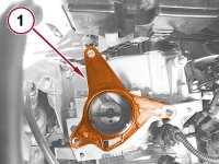
6. Remove the upper rigid pipe bracket fixing screw (1).


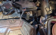
7. Disconnect the air pressure sensor electrical connector (1).


8. Loosen the clamp and remove the rigid pipe (2) if you did step #6 above; otherwise just disconnect where this clamp was and push pipe out of the way

9. ONLY LOOSEN the 10mm bolt (1) securing the bracket to the valve cover. Quite tight space so don’t try to remove this.


10. Disengage the upstream oxygen sensor wiring (---->) (1).


11. Remove the engine oil vapor separator retaining screw (2 above)

12. Disengage the wiring retaining clips (1).

13. Unscrew the fasteners (2) and remove the wiring bracket.

(The removed bracket showing where 10mm bolts and nut are located; oxygen sensor clip; retaining clip holes)
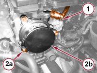
14. Disconnect the outlet hose quick coupling (1) for the brake booster vacuum by pressing the button.


15. Remove the screws (above 2a) and remove the turbo vacuum pump (above 2b) along with the gasket. Torx T45 screws.

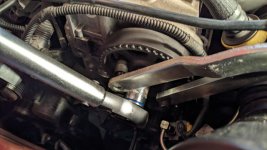
16. Install the Camshaft Timing Locking 10277 (NAFTA) tool. (1)

Before I could install this tool, I needed to slightly turn the camshaft pulley clockwise using the cam pulley holder tool (see step #21).


When installing the alignment tool, have the inner 2 bolts loose and tighten the outer three first. Then do the inner 2.

17. Remove the air cleaner assembly. Undo 3 Phillips head screws (these will not come out of the plastic cover), undo the clip on air hose, pull out air filter, pull out the tray.


18. Pop off 500X wheel nut cover with flat screwdriver.

19. Loosen wheel nuts (17mm socket) on air filter side. Chock back wheels. Raise the front of the car. Place on jack stands.


20. Remove the right front wheel and splash shield (flat screw driver, Phillips head, Torx T20, 10mm socket).


21. Remove 2 bolts securing cover for cam shaft pulley. The second one is around the side.
Then pry out the cable from the groove.
If at step 16 the cam locking tool didn’t fit, this is where you need to slightly rotate the pulley.


22. Remove the belly pan by undoing four 10mm bolts and 2 Torx T20 screws on the wheel guard under the battery side.

23. Support the engine and transmission with jacks.

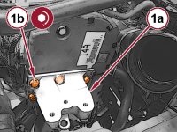
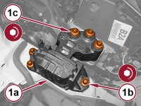
24. Remove screws (1a and 1b), then remove the engine mount (1c), timing side.


25. Remove the 5 bolts (1a) and remove the rigid support (1b), timing side. Mine has three bolts underneath and 2 on top. A short extension arm is useful.


26. Remove the screws (1a) and remove the bottom protection cover (1b). Pull out the wiring harness from groove within the cover.


27. Mark the direction of serpentine belt.

28. Rotate the tensioner anticlockwise to loosen and pull off belt.

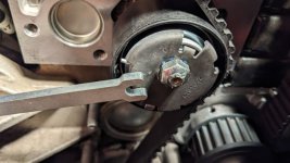
29. Remove the crank pulley by undoing three 13mm bolts. Hold cam shaft pulley with holder, you can't just rely on the cam holding tool. You risk destroying the cam shaft.

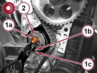
30. Install the 2000004500 (EMEA) or Crankshaft Timing Locking 10276 (NAFTA) tool (1). It should line up perfectly.


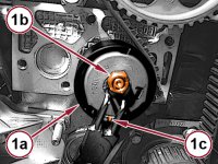
31. Loosen the nut (1a) of the tensioner and remove the timing belt (1b). This is a specialty nut so don’t loose it.


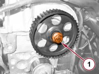
32. You must secure the pulley with the cam pulley holder tool. Then loosen the pulley retaining screw (1). If you skip this step, the tensioner will not be able to tension the belt correctly.


33. Put bucket under the water pump. Undo three 10mm bolts and one 10mm nut. Pull off water pump.
34. Clean the surface off rust & sealant.
35. Apply PERMATEX and install new water pump. Do not fill with coolant for 24 hours.
PMX-82180 Permatex Ultra Black Maximum Oil Resistance RTV Silicone Gasket Maker

If not done correctly, you will damage the engine at your own risk. This worked for me, may not work for you.
NOTE: When replacing the timing belt, connect the diagnostic tool, enter "Diagnosis active" and run the self-learning procedure.
1. Remove the engine beauty cover: 10mm bolts
2. Remove the battery: 10mm nuts on terminals and 13mm nut low
Take out liner and remove13mm bolts securing the battery tray
3. Slip off plastic clips securing washer bottle & negative battery terminal; remove battery tray
4. Remove the low nut securing rigid pipe (1) in front of the engine.
5. I didn’t need to loosen the lower clamp, but you could if you wanted to disconnect the hose from the rigid air pipe (2) above.
6. Remove the upper rigid pipe bracket fixing screw (1).
7. Disconnect the air pressure sensor electrical connector (1).
8. Loosen the clamp and remove the rigid pipe (2) if you did step #6 above; otherwise just disconnect where this clamp was and push pipe out of the way
9. ONLY LOOSEN the 10mm bolt (1) securing the bracket to the valve cover. Quite tight space so don’t try to remove this.
10. Disengage the upstream oxygen sensor wiring (---->) (1).
11. Remove the engine oil vapor separator retaining screw (2 above)
12. Disengage the wiring retaining clips (1).
13. Unscrew the fasteners (2) and remove the wiring bracket.
(The removed bracket showing where 10mm bolts and nut are located; oxygen sensor clip; retaining clip holes)
14. Disconnect the outlet hose quick coupling (1) for the brake booster vacuum by pressing the button.
15. Remove the screws (above 2a) and remove the turbo vacuum pump (above 2b) along with the gasket. Torx T45 screws.
16. Install the Camshaft Timing Locking 10277 (NAFTA) tool. (1)
Before I could install this tool, I needed to slightly turn the camshaft pulley clockwise using the cam pulley holder tool (see step #21).
When installing the alignment tool, have the inner 2 bolts loose and tighten the outer three first. Then do the inner 2.
17. Remove the air cleaner assembly. Undo 3 Phillips head screws (these will not come out of the plastic cover), undo the clip on air hose, pull out air filter, pull out the tray.
18. Pop off 500X wheel nut cover with flat screwdriver.
19. Loosen wheel nuts (17mm socket) on air filter side. Chock back wheels. Raise the front of the car. Place on jack stands.
20. Remove the right front wheel and splash shield (flat screw driver, Phillips head, Torx T20, 10mm socket).
21. Remove 2 bolts securing cover for cam shaft pulley. The second one is around the side.
Then pry out the cable from the groove.
If at step 16 the cam locking tool didn’t fit, this is where you need to slightly rotate the pulley.
22. Remove the belly pan by undoing four 10mm bolts and 2 Torx T20 screws on the wheel guard under the battery side.
23. Support the engine and transmission with jacks.
24. Remove screws (1a and 1b), then remove the engine mount (1c), timing side.
25. Remove the 5 bolts (1a) and remove the rigid support (1b), timing side. Mine has three bolts underneath and 2 on top. A short extension arm is useful.
26. Remove the screws (1a) and remove the bottom protection cover (1b). Pull out the wiring harness from groove within the cover.
27. Mark the direction of serpentine belt.
28. Rotate the tensioner anticlockwise to loosen and pull off belt.
29. Remove the crank pulley by undoing three 13mm bolts. Hold cam shaft pulley with holder, you can't just rely on the cam holding tool. You risk destroying the cam shaft.
30. Install the 2000004500 (EMEA) or Crankshaft Timing Locking 10276 (NAFTA) tool (1). It should line up perfectly.
31. Loosen the nut (1a) of the tensioner and remove the timing belt (1b). This is a specialty nut so don’t loose it.
32. You must secure the pulley with the cam pulley holder tool. Then loosen the pulley retaining screw (1). If you skip this step, the tensioner will not be able to tension the belt correctly.
33. Put bucket under the water pump. Undo three 10mm bolts and one 10mm nut. Pull off water pump.
34. Clean the surface off rust & sealant.
35. Apply PERMATEX and install new water pump. Do not fill with coolant for 24 hours.
PMX-82180 Permatex Ultra Black Maximum Oil Resistance RTV Silicone Gasket Maker
Installation
NOTE: When the belt must be handled and mounted, avoid creating bends at an acute angle. This can compromise the structure of the belt, as the stresses induced by excessive bending could result in damage to the fibers inside the belt, which could cause premature failure of the belt during operation of the engine.

NOTE: Install the timing belt, aligning it initially on the crankshaft gear, water pump pulley, camshaft gear, and finally the tensioner.
1. Bring the timing belt to the maximum tension by turning the tensioner (1a) counterclockwise and secure with the nut (1b) when the alignment reference (1c) is in the position. Tighten the nut (1b) to 25 Nm or 19 Foot Pounds.


2. Hold the camshaft pulley with the tool. Then tighten the camshaft pulley retaining bolt (1) to 120 Nm or 89 Foot Pounds.


3. Remove the valve timing tools mounted to the camshaft and crankshaft.
4. Perform two turns of the crankshaft.
5. Loosen the nut securing the tensioner and align the notch.

6. Tighten the tensioner nut to the proper torque.
7. Turn the crankshaft in the normal direction of rotation two more turns, then recheck tensioner.
8. Install the bottom protection cover and tighten the screws.
9. Install the top protection cover and tighten the screws.
10. Engage the wiring to the retaining clips.
11. Close the fuel vapor hose retaining clips.
12. Put the support into place (1a), timing side and tighten the screws (1b) to 25 Nm or 18 Ft lbs.

13. Put into place the elastic engine mount block (1a), timing side, tighten the screws (1b and 1c). All bolts 60Nm or 44 Ft lbs

14. Remove the supports under the engine.
15. Install the crank pulley M8 Bolts 25Nm or 19 Ft lbs
16. Install the air cleaner assembly.
17. Install the right front wheel and splash shield.
18. Install a new gasket for vacuum pump.

19. Install the vacuum pump (1a) and tighten the screws (1b)

20. Connect the quick coupling outlet hose for the vacuum brake booster.
21. Install the wiring bracket and tighten its hardware.
22. Engage the wiring retaining clips.
23. Tighten the engine oil vapor separator screw.
24. Engage the upstream oxygen sensor wiring.
25. Tighten the screw securing the bracket to the valve cover.
26. Install the rigid pipe in to the throttle body and tighten its strap.
27. Connect the air pressure sensor electrical connector.
28. Tighten the mounting screw for the rigid pipe between the cooler and throttle body to bracket.
29. Connect the air sleeve to the rigid pipe between the cooler and throttle body and tighten strap.
30. Tighten the nut securing the rigid pipe between the cooler and the throttle body to the bracket on the gearbox.
31. Install the belly pan.
32. Install the battery.
33. Install the engine beauty cover.
I also changed: oil & filter, air & cabin filters, rear engine mounts,
NOTE: Install the timing belt, aligning it initially on the crankshaft gear, water pump pulley, camshaft gear, and finally the tensioner.
1. Bring the timing belt to the maximum tension by turning the tensioner (1a) counterclockwise and secure with the nut (1b) when the alignment reference (1c) is in the position. Tighten the nut (1b) to 25 Nm or 19 Foot Pounds.
2. Hold the camshaft pulley with the tool. Then tighten the camshaft pulley retaining bolt (1) to 120 Nm or 89 Foot Pounds.
3. Remove the valve timing tools mounted to the camshaft and crankshaft.
4. Perform two turns of the crankshaft.
5. Loosen the nut securing the tensioner and align the notch.
6. Tighten the tensioner nut to the proper torque.
7. Turn the crankshaft in the normal direction of rotation two more turns, then recheck tensioner.
8. Install the bottom protection cover and tighten the screws.
9. Install the top protection cover and tighten the screws.
10. Engage the wiring to the retaining clips.
11. Close the fuel vapor hose retaining clips.
12. Put the support into place (1a), timing side and tighten the screws (1b) to 25 Nm or 18 Ft lbs.
13. Put into place the elastic engine mount block (1a), timing side, tighten the screws (1b and 1c). All bolts 60Nm or 44 Ft lbs
14. Remove the supports under the engine.
15. Install the crank pulley M8 Bolts 25Nm or 19 Ft lbs
16. Install the air cleaner assembly.
17. Install the right front wheel and splash shield.
18. Install a new gasket for vacuum pump.
19. Install the vacuum pump (1a) and tighten the screws (1b)
20. Connect the quick coupling outlet hose for the vacuum brake booster.
21. Install the wiring bracket and tighten its hardware.
22. Engage the wiring retaining clips.
23. Tighten the engine oil vapor separator screw.
24. Engage the upstream oxygen sensor wiring.
25. Tighten the screw securing the bracket to the valve cover.
26. Install the rigid pipe in to the throttle body and tighten its strap.
27. Connect the air pressure sensor electrical connector.
28. Tighten the mounting screw for the rigid pipe between the cooler and throttle body to bracket.
29. Connect the air sleeve to the rigid pipe between the cooler and throttle body and tighten strap.
30. Tighten the nut securing the rigid pipe between the cooler and the throttle body to the bracket on the gearbox.
31. Install the belly pan.
32. Install the battery.
33. Install the engine beauty cover.
I also changed: oil & filter, air & cabin filters, rear engine mounts,
Torque Settings
| Nm | Ft lb | |
| Accessory Belt Tensioner - M8 Bolt | 26 | 19 |
| Crankshaft Sprocket - M12 Bolt | 20 + 110° Turn | 15 + 110° Turn |
| Crankshaft Vibration Damper - M8 Bolts | 25 | 19 |
| Tensioner to Cylinder Head - M8 Nut | 28 | 21 |
| Camshaft Sprocket - M12 Bolt | 120 | 89 |
| Engine Mount to Frame Rail - M10 Bolts | 60 | 44 |
| Engine Mount to Engine Bracket - M10 Bolts | 60 | 44 |
| Engine Mount Bracket to Cylinder Head - M8 Bolts | 25 | 18 |
| Rear Engine Mount to Crossmember Bolt (runs across) | 55 + 90° Turn | 41 + 90° Turn |
| Rear Engine Mount to Transaxle Bracket Bolt and Nut | 80 + 45° Turn | 59 + 45° Turn |
| Transaxle Bracket to Manual Transmission - 3 x M8 Bolts and Nut | 80 | 59 |
| Transmission Mount Bracket to Transmission - M8 Bolts | 50 | 37 |
| Transmission Mount to Frame Rail Bolts | 100 | 74 |
| Transmission Mount to Transaxle Bracket Bolts | 100 | 74 |
| Oil Pan Drain Plug | 27 | 20 |
| MultiAir Actuator Oil Supply Filter - M18 | 27 | 20 |
| Spark Plug Tube to Cylinder Head - M28 | 45 | 33 |
| Coolant Pump to Engine Block - M6 Bolts | 10 | - |
| Coolant Pump to Engine Block - M6 Nuts | 10 | - |
| Engine Oil (1.4L) SAE 5W-40 API MS-12991 Shell Helix Ultra ECT C2/C3 | 3.8 Liters | 4.0 Quarts |
| Spark Plugs (1.4L Engine) | 0.65 mm | 0.026 in |