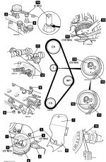
Installation

1. Hold camshaft sprocket. Use tool No 1860831000 [14].
2. Slacken camshaft sprocket bolt [15]
3. Ensure piston position tools fitted correctly into cylinders No.1 & No.2 [9].
& Ensure locking tools fitted correctly to each camshaft [12].
5 Fit timing belt in anti-clockwise direction, starting at crankshaft sprocket Ensure belt is taut between sprockets on non-tensioned side.
6. Turn tensioner pulley until mark at maximum tension position [16]. Use tool No. 1860987000
7. Tighten tensioner nut to 25 Nm [13]
8. Hold camshaft sprocket. Use tool No 1860831000 [14].
9. Tighten camshaft sprocket bolt to 120 Nm [15j
10. Remove locking tools from camshafts [12] Remove piston position tools [9]
11. Turn crankshaft two turns clockwise to setting position
12. Temporarily refit crankshaft pulley Check alignment of dowel pin opposite crankshaft position (CKP) sensor [1]
13. Slacken tensioner nut [13].
14 Turn tensioner pulley until marks aligned [17] & [18] Use tool No. 1860987000
15 Tighten tensioner nut to 25 Nm [13].
16. Turn crankshaft two turns clockwise to setting position.
17. Screw piston position tools into cylinders No.1 & No.2 [9] Tool No. 1860992000. Tightening torque: 5 Nm.
18. Turn crankshaft slightly until notches of both tools aligned with upper surface [10].
19. Ensure slots in camshafts are aligned with blanking plug holes [11]
20. Ensure locking tools fit easily to each camshaft [12]. If not: Repeat installation and tensioning procedures.
21. Install components in reverse order of removal
22. Tighten crankshaft pulley bolts [3]. Tightening torque: 22 Nm
23. Ensure crankshaft position (CKP) sensor air gap is 0.5-1,5 mm [19].
Stains Addition
24. turn engine 2 complete crank revolutions, in direction of rotation, BY HAND before starting with the key to ensure it will turn 'freely'.

