Technical Urgent help needed! Weird problem with my '05 x244 van.

Currently reading:
Technical Urgent help needed! Weird problem with my '05 x244 van.

So, finally some good news.

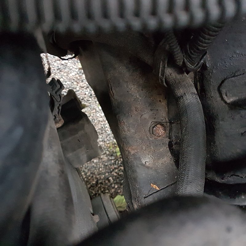
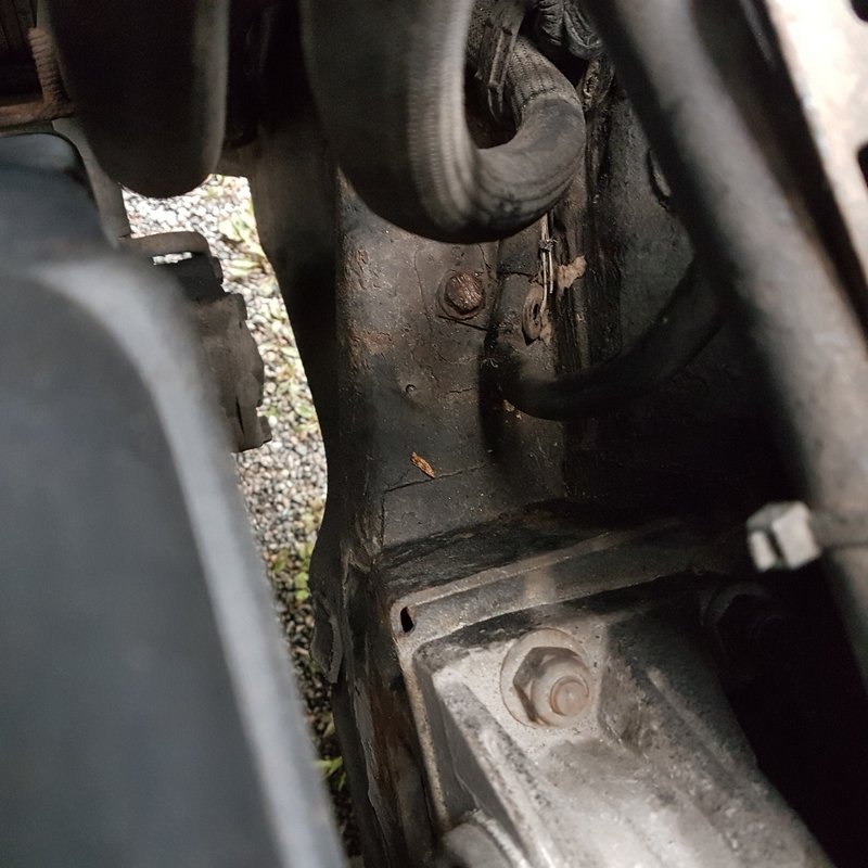
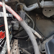
The fuel pump not priming was indeed due to the inertia switch being activated. Below is how I found it initially, just dangling downwards at the back.

Also, notice the broken mount on the switch.


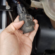
I mounted it securely at an upright position, clicked the button back to place and... lo and behold, the fuel pump was back to work happily.

Good news indeed.

=======================================================
But it gets even better: I managed to fix the central locking system! After wiring back the unit and supplying 12v and earth, it all came back to life.

Yes, more good news.

========================================================


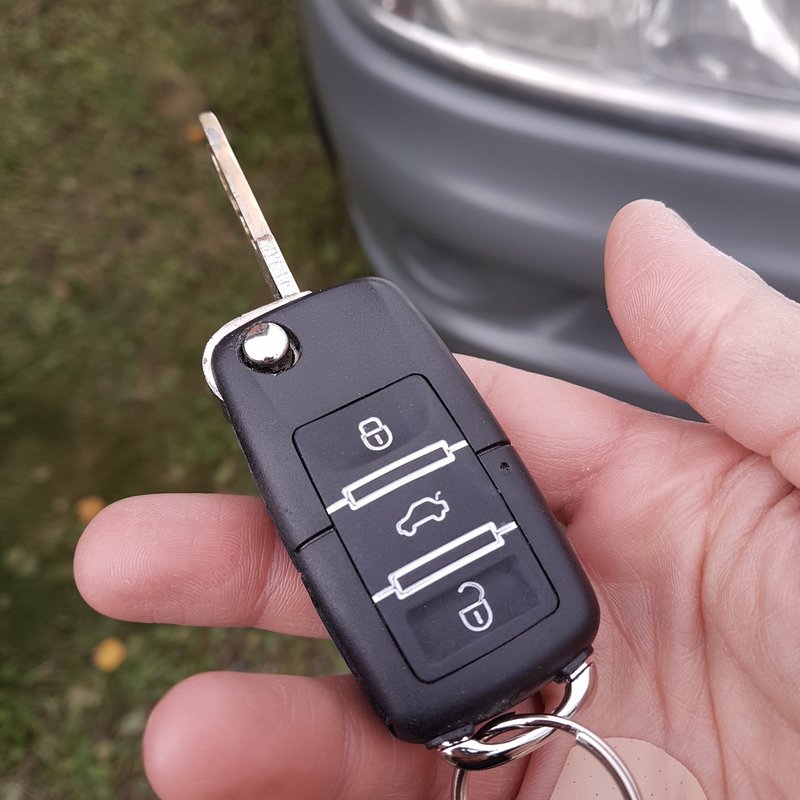
Now, I think I will just get a remote fob to control the locks and call it a day.


If not already done, you will have to refit the Cobra unit, or replace with a Fiat alarm unit and receiver + Fiat key fobs, which could be expensive, and difficult to install. See link.

http://4cardata.info/elearn/244/2/244000001/244000003/244000005/244002006

========================================================

Comm, I did check the alternator on several occasions and it is showing around 14.3 to 14.4v on tick over.

Noted. I do not recall this being mentioned previously.
 
Comm, a small question if I may; why would I have to refit the Cobra alarm to have a remote locking capability?

There are small aftermarket units that do exactly that thing. In particular I've found the following for 20-30 euro.
2017012705364321-913810.jpg


People who installed it mention that it's a simple wiring job. From the instructions it seems to be piggybacking onto a working central locking system (which I now have (y) ) and activating the locking mechanism.
2017012705370375-913810.jpg


2017012705371257-913810.jpg


The only issue now is to find which of the above three (neg trigger, pos trigger, both) is the one applying to the x244.
 
Nick,

As you seem to have found a suitable remote control unit, you will not need to replace the whole alarm system.

To answer your query, as I read it on eLearn diagram E3040, and descriptive text, the operating signal from the lock is a switched negative.

It is not clear to me as to why removing your Cobra interface relays, disabled your central locking. I could conjecture that perhaps that is one function of the Cobra system, when the alarm is activated. I can visualise you using both the proposed remote system, and the Cobra relays in tandem. More complications equals less reliability. Perhaps some further wire tracing, coupled with eLearn diagram E3040 may yield further understanding and the removal of the Cobra relays. Please note a major error on my copy of E3040 is the depiction of the sliding door lock as a closed contact, which would short out all of the lock motors. What should be shown is a lock motor, like the adjacent item N154, which is the lock motor for the RHS rear door.
 
Nick,

As you seem to have found a suitable remote control unit, you will not need to replace the whole alarm system.

To answer your query, as I read it on eLearn diagram E3040, and descriptive text, the operating signal from the lock is a switched negative.

It is not clear to me as to why removing your Cobra interface relays, disabled your central locking. I could conjecture that perhaps that is one function of the Cobra system, when the alarm is activated. I can visualise you using both the proposed remote system, and the Cobra relays in tandem.

That's exactly how I have thought it might be. The alarm was splicing into the brown and white wires of the interface relay, so my hunch is that the brown and white are responsible for triggering the lock/unlock signal to the central locking system. I am planning to use both the current interface and the new one in tandem; in theory that should not pose any problems.

On the new interface, the first wiring diagram refers to negative trigger; I suppose that's the one I need to utilise. Does "non-connect" mean do not connect this wire? (Chinese English is not my strong suit... :p )

More complications equals less reliability. Perhaps some further wire tracing, coupled with eLearn diagram E3040 may yield further understanding and the removal of the Cobra relays. Please note a major error on my copy of E3040 is the depiction of the sliding door lock as a closed contact, which would short out all of the lock motors. What should be shown is a lock motor, like the adjacent item N154, which is the lock motor for the RHS rear door.

As it is, the current interface is triggering everything; it locks the doors but also the sliding door. What are the brown and white wires? If the system is negative trigger, are they carrying the ground to close the loop? I am asking because I measured them but I couldn't find any current running through them.
 
That's exactly how I have thought it might be. The alarm was splicing into the brown and white wires of the interface relay, so my hunch is that the brown and white are responsible for triggering the lock/unlock signal to the central locking system. I am planning to use both the current interface and the new one in tandem; in theory that should not pose any problems

=========================================================


On the new interface, the first wiring diagram refers to negative trigger; I suppose that's the one I need to utilise. Does "non-connect" mean do not connect this wire? (Chinese English is not my strong suit... :p )

That is how I would understand it.

=========================================================


As it is, the current interface is triggering everything; it locks the doors but also the sliding door. What are the brown and white wires? If the system is negative trigger, are they carrying the ground to close the loop? I am asking because I measured them but I couldn't find any current running through them.

Nick,

I do not think that I can answer youy last question without further information. As I have already suggested you could expect your Cobra interface relays to have two input, and two output connections, plus power supply. If you want to investigate more, you will have to do more wire tracing, and perhaps see where the wires connect to on the relay board. Not easy if you are not used to it. Perhaps photos of both sides of the board? If you are intending to connect via the Cobra relays, you will need to know whether the inputs are +ve or -ve triggered, and at what voltage if they require a +ve input.
 
Do you think I could just put the multimeter on the brown and white wires and measure their voltage while activating/deactivating the locks? Would that work?

Edit: Actually I think I've answered my own question. A little research on the interwebs revealed some valuable information on installing such systems and how to specifically test for IDing the wires to use.

https://www.deviousweb.com/wp-conte...SHI-FTO-How-to-Fit-a-Keyless-Entry-System.pdf

https://static.summitracing.com/global/images/instructions/hfm-kl550.pdf

I'll wait until I can get my paws on the new system and report back. (y)
 
Last edited:
Just throwing this out there...

From experience...the machine gun buzzer noise sounds like a relay.
They shouldn't buzz.

But The missing dash lights...a bad earth?


I take it you can unlock the van with your electronic key with button press?
The standard immobilizer required your key to work.
The cobra alarm may be the issue....

Definitely try the new Earth suggestion....after the charged battery is installed!

Maybe your starter motor or solenoid or fuel pump is faulty?

Multiecuscan may shed some light. Maybe there is an error code?
 
All good advice IceVovo; thanks.
Regarding the buzzing, it was indeed the hazard lights relays. The reason they were buzzing was because they were getting extremely low voltage. If that was due to the battery or something else, that is uncertain.

If you go through the thread you'll see that I checked most things that were suggested and they all checked out. As for the Cobra alarm, I successfully got rid of it, so that's one less thing to worry about. About the new earth connection, do you have a suggestion how to go about it? (ie, what kind of cable to install and where to mount it)

I don't have a Multiecuscan system and I'm a bit wary of going to the dealers for obvious reasons...
 
Hey all, today I had an interesting development.
This morning I went to take the car after not using it for 2 days and again it wouldn't start. It was doing the usual dance; dashboard lights et ok, engine refused to turn over.

I put the multimeter to the battery to read the voltage; 12.51 v.
So I thought it would be a good idea to measure the draw to the battery while trying to start the car. I put the probes to the poles of the battery and I had my wife turn the key to start the engine.

The engine did not turn over, BUT to my surprise, I heard a few sparking sounds from the probes where they were touching the battery and I saw the ground wire putting out a little ...smoke?? It was not scary or dangerous; just a little wisp of smoke came out from the cable's core (the metallic wiring, NOT the insulator).

Curious to see if I could replicate this behaviour I had my wife turn the key once more and the engine fired up immediately! What is that? To me it points directly to a dodgy ground cable (we have already eliminated the possibility of a bad battery).
Could anyone who had issues with the grounding on their vans chip in here?

If it is indeed the grounding cable what would be the best fix? Should I replace the wire with another from a x244, or should I add another ground wire? If the latter, how should I go about doing so? (mounting place, wire thickness etc)
 
Hi

I think you may have finally found your problem. Sounds like you have a bad connection somewhere in the ground lead of the battery. This could be anywhere that two parts are joined together, like a crimped joint, a bolted joint, a quick release battery clamp etc. The tarnishing or corrosion may not be visible. Sometimes moving the connection will cure it temporarily.

If there is a high resistance (bad connection) and a large current flows through it, it will generate heat. If this goes on long enough, the temperature can rise enough to cause smoke from any oil, grease or plastic in contact.


The ideal thing would be a new replacement cable from Fiat

But you could source a replacement from an Auto Electric specialist. They may be able to make you one, as they will have all the parts to assemble together and the right tools to do large crimp joints.


The main thing is that the cross sectional area (CSA) of the cable must be big enough to suit a starting circuit for a medium to large sized diesel engine. I would recommend 50 square mm minimum, 70 square mm would be better. To give an idea, a 70 square mm CSA round cable has a conductor diameter of about 10mm. The insulator will add about another 2 mm, so the overall cable diameter will be 12mm, about as thick as your little finger. The original cable may be thinner, but Fiat are saving money whereas you are trying to do a decent job (I hope !)


When you put things together, all the metal touching surfaces of the connections must be bright clean before assembly and then properly tightened.


Both battery connections are also worth checking. The lead posts on the battery, and the inside of the clamps, should be wire brushed till they are bright clean. If you have quick release battery clamps, make sure they are actually tightening enough.
 
Prime suspect all along revealing itself......Fiat earthing can be flaky, but a relatively easy fix. Earth leads should be easily available at any parts store- just buy the right size, length and terminal types, replace in same positions as old ones having cleaned mating surfaces. Bare braided ones may not be available, so plastic insulated is OK, beware of water ingress between sleeve and wire within over time, you should be fine.
 
Last edited:
Hi Nick,

I have measured the external diameter of the earth cable on my 2006 2.8jtd. The result suggests 50 sq mm conductor csa. eLearn however is inconsistent quoting 35 sq mm at one end and 50 sq mm at the other end of the same cable. That is if I have read eLearn correctly. 50 sq mm matches Anthony's recomendation above.

However since the problem seems to be at the crimp terminal on the battery there are other possibilities and factors when considering replacement.

Replacing the whole length of cable as far as the starter motor stud on the clutch housing could be difficult if run on the same route as the original. It may involve moving the radiator and or the intercooler under which the cable is routed.

Option 1. Replace the whole cable to match the original installation.

Option 2. Replace with 50 sq mm cable, only the much shorter length from the battery to the main chassis earth point. (Remove the redundant section of cable.)

Option 3. Replace with two separate cables. First a 50sq mm cable to the starter motor stud only from the battery, and second a 25 or 35 sq mm cable between the main chassis earth point and the battery.

Option 2 would be much easier to install, but the connection between the two cables, at the main chassis earth point would be vital. The state of the existing cable and connection at the earth point would have to be carefully examined.

In option 2 the smaller cable would only be carrying load current taken by the vehicle electrics and ECU. The heater fan is probably the largest single load. If a heat flange is fitted for cold starting instead of a thermal starter, I would expect it to draw a larger current.
 
Hi all. Thanks once more for taking the time to help and for all the great info.

I just went outside to take a couple pics of the grounding cable in more detail and to my great disappointment, replacing even a section of it seems to be a bit of a task.

Initially I thought that the wire runs from the battery to the chassis point and from there another wire runs to the starter motor. However, it seems that the wire is one piece running from the battery to the starter with a crimped connection in between which attaches to the chassis.

If I had access to a garage/shed I would happily take everything apart and remove the cable completely; however I'm working out in the open and my window of opportunity has passed. From today onwards and at least for the next 15 days there will be rains/showers and low temps (the joys of Finnish climate :yuck: )

Comm, cheers for taking the time to check your cable and for all the great suggestions. In option #2 , did you mean to cut the existing cable from the chassis point to the battery pole and put an aftermarket one in place?

I agree with everyone, my preference would be to change the whole thing out; however as mentioned above I just don't have the conditions to do anything meaningful anymore.

Have a look at the pics of the grounding wire and tell me if I could do something quick and dirty to improve the situation.

Chassis ground point:
20200903-080218.jpg


Another view
20200903-080107.jpg


Battery pole connection
20200903-075936.jpg
 
Last edited:
Hi

You reported smoke near the terminal. The two weak points are the joint from battery terminal to clamp, and the joint from clamp to cable. I assume you have checked out the battery terminal to clamp joint by removing and cleaning. That leaves the joint from clamp to cable.


I suggest you remake this connection between the cable and the battery clamp. Cut 20 mm off the cable core (assuming there is enough slack), clean up the strands and the clamp inner with abrasive paper until they are shiny and reassemble. The "saddle" MUST be really tight on the cable. If it is not tight, you might need to pack with a piece of clean copper. Maybe cut from scrap water pipe ?


That clamp doesn't look original to me. If you can get a new aftermarket clamp that would be better.

In the long term, the joint to the chassis should also be sorted. It looks rather weathered.
 
Saturday morning I'll go to a shop nearby and I'll get an aftermarket clamp. Anthony, is a 50mm wire clamp ok or will I need the 35mm version?

Unfortunately, there will be showers all weekend but I'll try to get it done. For what is worth, I just moved the van and it fired up immediately.

Varesecrazy I only tried the jumper cable the time when I took the battery out to fully charge it. It may have contributed to the van working, but I don't know. Seeing as the ground wire might be the culprit here I think I need to properly address it at some point down the line.

Unfortunately whatever time I had available to work on the van has expired; from now on the weather will be quite nasty and in about 10 days I will have to do a cross continental trip. My hope is that when I get to warmer climes I can finally strip down the front of the car and swap out the cable completely.
 
So, to wrap things up, as promised I swapped out the ground wire clamp with a brand new one. Following Anthony's advice I cut off a bit of the old wire core which was weathered and dirty, and I sanded/cleaned the strands thoroughly. Then I fitted the new and shiny clamp and tightened all the bolts. I don't know if this will fix all my troubles but it sure looks good! :)
20200905-152058.jpg


I also removed the joint to the car's chassis which admittedly did not look too bad on the inside. Be that as it may, I sanded down the bare metal, cleaned it all up and refitted the 13mm bolt. For now at least the car is fixed; it starts up happily every time.

Ps. Did I mention that I fitted the new remote central locking system the other day? Now the car has a fancy new set of keys.
For 20 euro it's well worth it. :)
20200905-152118.jpg
 
Last edited:
user77

Welcome.

It was sounding like a bad earth as you had DOA symtoms. "no lights on the dash".

New setup is looking good???
Clean up of all the earths. cool. :)

However...
Your negative setup is looking different to mine? Is this a 2005 to 2006 difference?
I have multiple earths running from that negative post on my 2006 model...


Obviously update us if the gremlin emerges.
 
Last edited:
IceVovo, thanks for the kind words and a bug thank you to everyone for pointing me to the right direction.

I've no idea re the negative setup; I don't know how it looks in other year models and the setup was like this when I got it.
However, the car is now running like a champ. As a matter of fact I drove straight through Europe, covering about 4000 km on 5 days. The car never missed a beat, driving in everything from sweltering heat to freezing cold and even through the torrential rain of a ...cyclone! It simply shrugged everything off. :)

All's well that ends well.
 
Back
Top