Technical clutch

Currently reading:
Technical clutch

Glad to hear you're not having problems returning your purchase and it would be good to know who the supplier is if all goes well - every little bit adds to our knowledge base.
Looking forward to your next post. Good luck with it all.
Jock.
Hi folks Does anyone know Torque settings for flywheel bolts please.
Just had a look in both my Panda and Punto Haynes manuals and both give a figure of 15Nm (10 lbs ft). Also found an on line site quoting 14Nm for 6mm clutch cover bolts on the 500. Also the Haynes manual advises to always renew the bolts? I doubt if tightness is super critical - not like a cylinder head or big end bolts? - I've often done them just by "feel" in the past, but I did earn my living for many years working on vehicles so you develop a good sense of how tight "tight" really is. Now a days renewing fixings is often recommended and I'd always do this with head bolts or bigend/main bearing cap bolts, I've not before come across a recommendation to replace clutch cover bolts on something as mundane as this? I know the bolts were reused on both our Panda and Punto when their clutches were done a couple of years ago. I very much doubt if a 15Nm torque setting is going to take a 6mm bolt into it's elastic range?
 
Hi all
Update to clutch repair
Finally got what appears to be the right clutch .
The company that supplied the last clutch and flywheel set did credit me for it in full and collected it foc were Atc on ebay

The idea was to replace clutch but also to remove refit leaking sump. Strangely sump leaking around the bolts
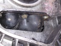
Turns out it seems impossible to replace sump without gearbox removal anyway. Note the bolt positions in photo 1 inside clutch housing .Unfortunately that's only the half of it. On removing the bolts all around the sump,I discover that the bolts are quite loose ,held by the sealant used to seal the sump. I then further realise the bolts have helicoils attatched to the threads. So clearly who ever refitted the sump last had overtightened into aluminium crankshaft block. then , did a crap job of helicoil repairs I.e half arsed mechanic with a rattle gun. Currently awaiting delivery of helicoil kit and hoping it not to bad i.e drilling out and tapping all those holes.
So still at it but weather and parts against me.
Gromit
 

Attachments

  • IMG_20220209_154937.jpg
    IMG_20220209_154937.jpg
    2 MB · Views: 40
Hi all
Update to clutch repair
Finally got what appears to be the right clutch .
The company that supplied the last clutch and flywheel set did credit me for it in full and collected it foc were Atc on ebay

The idea was to replace clutch but also to remove refit leaking sump. Strangely sump leaking around the bolts
Turns out it seems impossible to replace sump without gearbox removal anyway. Note the bolt positions in photo 1 inside clutch housing .Unfortunately that's only the half of it. On removing the bolts all around the sump,I discover that the bolts are quite loose ,held by the sealant used to seal the sump. I then further realise the bolts have helicoils attatched to the threads. So clearly who ever refitted the sump last had overtightened into aluminium crankshaft block. then , did a crap job of helicoil repairs I.e half arsed mechanic with a rattle gun. Currently awaiting delivery of helicoil kit and hoping it not to bad i.e drilling out and tapping all those holes.
So still at it but weather and parts against me.
Gromit
Oh man, you must have done something really wicked in your past life to be deserving this. (Ha Ha). If you find the threads in the casting (now oversize to accept the helicoils) are too badly damaged to accept new helicoils then have you heard of Time Serts? Made by Wurth: This video shows how they are used and I prefer them to Helicoils as they tend to stay put - especially for stuff like sump plugs in ally sumps. (Although there are some very good and quite cheap oversize plug kits available as long as there's enough "meat" left in the sump metal to use them). Many people don't know that they, Wurth, also make a product called a "Big Sert" which is the same basic idea but with a thicker sidewall so you can recut the hole in the casting to the next size up, wind in the Big Sert and end up with your original thread size! Wurth themselves are a bit "sticky" about selling to the general public from their shops wanting to deal with "trade only" but you can buy their stuff on line without too much agro or, as I do, get a friend who still works in the trade to buy for you. They are a bit more expensive than helicoils, and I think the range of sizes/threads is more limited, but, if they do the size you need it can be a real life saver.

It's worth (no pun intended!) knowing that brake caliper guide pin threads can be repaired in a very similar way: In fact the N/S/F top guide pin on my Ibiza has been very successfully repaired using one of these - although it was a Laser branded kit owned by my local garage we used.

Time Serts have been around for years and, as always, there are copy cat versions based on the same solid insert idea. I've never used anything except Helicoils and Wurth Time Serts so I can't say how well the cheaper versions work. What I have seen in adverts for them though is that some don't seem to come with such good tools included which might make installation of the insert more difficult?

So, chin up and keep drinking lots of tea!
and please do keep on updating us on your "adventure"
Kind regards
Jock
 
Hi all Ok another update
Sump removal . You would think that was straightforward .
Under the sump is the exhaust on that exhaust is a clamp right under the sump. It was obvious that clamp removed , sump would come off . In trying to remove the clamp I find that even loosened right off I could not move the clamp it would not spin it would not knock along the pipe. After taking a grinder to it I discovered that it was welded to the top of the exhaust . Due to its position I had to take a hacksaw blade to it. When it finally dropped off I was left with a small fagburn size hole in the exhaust pipe. This hole will easily be repaired with the right type of exhaust clamp and paste etc. Sump came off easily and I have cleaned it and can now repair sump bolt threads in block
Question can anyone work out what damaged the inside of the sump
See photos in next post
 
This is the clamp and next is marks inside sump no marks on outside?


IMG_20220128_100806~2.jpg


IMG_20220222_172416.jpg
 
This is the clamp and next is marks inside sump no marks on outside?


View attachment 402884


View attachment 402885
Those marks are a bit "disturbing" aren't they! They'd be worrying me too. I'm intrigued by the crease running across the sump just below them too and the mark below it. Having just spent the day childminding a 2 year old and his excitable sister (up at 6.00 and back home about 20.00hrs) We - Mrs J and I are completely Pugglt so I'm going to sleep on this before possibly offering an opinion. - G'night all!
 
Hi puggit
I regularly call my wife Mrs J We been married for 32 years and our surname is Jones . Just a ccoincidence . Anyway crease is a bump underneath and marks are at alternater end. Still scratching my head on that one myself . May have occurred when I tried to gently force it off before I moved that exhaust bracket.
It would be hard to catch it on oil strainer. Could have been caused by last person to fit it. All opinions gratefully received.
 
Another update all
I am of the opinion that marks in the sump are from the crease being beaten out. Nothing from under engine could have caught it. Anyway forced to remove exhaust from welded bracket point to get at bolt into gear box from behind.
Have now been struggling to get gearbox on for it seems like forever . Been close a couple of times. Changing tack today and ropeing it up so I can lift it in a sling and see if that works .ah well hey ho. Gromit
 
'Mornin gr0mit! I have to say top marks to you for perseverance! It's strange how some boxes just seem to slip back into place as easy as you like whilst others put up a hell of a fight. In my experience it's often down to how well the driven plate is centralized on the flywheel. Did you use a centralizing tool or line it up by eye? If the splines are quite course - i.e. relatively few splines - it can be difficult to get them to line up but the one's I've done had quite fine splines - i.e. many of them - and they usually can be made to line up quite easily. Might be worth taking a very careful look at the driven plate splines in relation to the hole in the middle of the flywheel - how well lined up are they? I've forgotten, your's is a diesel isn't it? On the petrol gearboxes there is no spigot on the input shaft so it doesn't actually locate in the flywheel. Because of this people think it's not so important to get the driven plate so accurately lined up with the centre of the flywheel. This is not true, it's just as important and if it's not lined up very accurately it makes refitting the gearbox very difficult or impossible.

Good luck. I'm "rooting" for you!

By the way, got you beaten on the marriage front - 50+ years for us and 8 years of "going out together" before that. I think we'll see it through to the end now! Ha ha. One of the best bits has definitely been the grandchildren who have turned me back into a kid on many occasions.
 
Hi all Thanks for the encouragement
Fortunately one of my great neighbors is a long retired engineer. When it came to alignment he got an old steel alignment tool he had made to fit a dinasoar many years previously. He turned it down for me to fit perfectly, so certain I have centered clutch. Splines on gearbox spindle fine and lots of em .
So the only thing I really need is me about 10 years ago, when I had muscles on my muscles. coincidentally we are having lunch out today with 2 of our grandchildren. Once again great neighbor will run us there.
Probably won't get another go at gearbox til later today or tomorrow .
Have a good day
Gromit
 
Hi all
Well gearbox is now on
Got to put it all back together now
My question is what is the minimum I can do to check that the clutch pedal works and gear changes are mechanically possible.
Bear in mind no gearbox oil ,engine oil and
Brake /clutch fluid yet.
Thanks gromit
 
Hi all
Well gearbox is now on
Got to put it all back together now
My question is what is the minimum I can do to check that the clutch pedal works and gear changes are mechanically possible.
Bear in mind no gearbox oil ,engine oil and
Brake /clutch fluid yet.
Thanks gromit
So the 'box is back on the engine but "dry"? there is likely to be a light coating of oil on the internal components still so running the engine briefly with the wheels off the ground - so no load on the internals - shouldn't cause problems. I wouldn't run it for long and I certainly wouldn't drive it without filling it with lub (obviously).

If you want to check it out with the car still up on stands I think you'll really need to get the hydraulics operational so you can push down on the clutch pedal and see if it's moving the release arm - Is yours one with an external slave cylinder or a concentric one inside the bell housing. Maybe the best way to get a meaningful result would be to put the driveshafts back in, select a gear and see what you get at the wheels. Block one wheel from turning either by dropping it to the ground or chocking it with a bit of wood or similar (otherwise the other wheel will turn opposite direction to the one you are turning by hand due to the diff and you may not realize because you may not notice!) - top gear will make it easier to spin the clutch driven plate. So, assuming the engine is not running, with the clutch pedal depressed, and assuming you've properly bled the clutch hydraulics, you should be able to quite easily rotate the road wheel. With the clutch pedal released the clutch should bit so with the engine not running and the other wheel chocked to stop it rotating, you should find you can't rotate the wheel.

Edit. Forgot to congratulate you! many apologies. Well done that man!
Hi All
having devils own job finding torque settings for hub nuts on my mk3 fiorino van.any help appreciated i am neaRLY THERE AND fed up now of giving wife a piggy back to the shops ???
 
Off hand I don't know your actual torque figure, but my Haynes manuals quote 240Nm for the Panda (169) and 70Nm plus tighten through 55 degrees for my boy's 2012 Punto. Can I assume these nuts are the "staked" type? (i.e. the edge of the nut is "bashed" over into a slot in the shaft to stop it loosening?) I know you are always supposed to renew this type of nut but I have in the past - more than once - simply reused the old nut and tightened it up until the "bashed" bit aligns with the groove in the shaft. This, of course, assumes there's a bit of nut flange still left to bash into the slot. I've often reused nuts by swapping them side for side which usually results in a new bit of flange being available to peen over.

Most garages will have a "Master" spec book (Autodata or similar) which will list torque figures like this, so if noone on here can help it could be worth asking a local garage? Your last resort might be to threadlock the nut and then simply tighten it as tight as you reasonably can with something like a power bar and bash as much flange over as you can. If you've done hub nuts before you'll have some "muscle memory" to assist with this. Modern wheel bearing assemblies are now pretty much all designed to achieve the correct preload on the balls/rollers when the nut is fully tightened. They achieve this because the outer race is in one piece and the inner races are machined so that when their inner faces come together the clearances/preloads on the balls/rollers is correct. I doubt if you could over tighten the retaining nut enough to increase the preload on the bearing and if you were to try - maybe with a long power bar and length of scaffold pole to help - I think either the nut would fail or the stub axle shear first. Of course undertightening may result in the nut coming loose - with predictably catastrophic results - and failing to tighten enough will allow too much play in the bearings which may lead to premature failure - In other words if you're not fully confident you can do it this way and know, for sure that the bearing assembly is the type of construction I've described above, then don't.
 
Hi puggit
I managed to do it by tightening as much as I could with a breaker bar and eventuallyg got the old peened over bits to lline up
I then steadily increased poundage per foot on a torque wrench and when I could not get it to click any more I rolled it back 4lb it clicked at 125 lb per foot .so just gotta double check and peen over. I did test drive and it is running nice . Starts first turn. What more could I want.
 
I would just like to take this opportunity to thank all here especially Puggit Auld Jock. Could I have done it without the help of this forum NO.
If anyone is going to try doing a clutch Andi can be of any help with phots etc ease ask.
Big Thanks Everybody.
Gromit
Hi puggit
I managed to do it by tightening as much as I could with a breaker bar and eventuallyg got the old peened over bits to lline up
I then steadily increased poundage per foot on a torque wrench and when I could not get it to click any more I rolled it back 4lb it clicked at 125 lb per foot .so just gotta double check and peen over. I did test drive and it is running nice . Starts first turn. What more could I want.
Congratulations! Glad to hear it seems to be running well.

Regarding tightening that drive shaft nut. If you've got the previous peened over bits to line up and this entailed "leaning" very hard on that power bar to do it you're probably somewhere around where you need to be. Are you saying that, even at the highest setting on your torque wrench, the nut never moved so you know the nut is at least 125 lbs ft tight? (125 lbs ft is probably a bit on the "light" side for a driveshaft nut) Trying to retrospectively discover a torque setting by applying a torque wrench to an already tightened nut and then steadily, incrementally, increasing the torque setting on the wrench until the nut just moves as the wrench clicks will not get anywhere even near to identifying the torque to which the nut was originally tightened. The problem is that the nut (or bolt) will adhere through friction to the face against which it's being tightened. So, to come back to a nut (or bolt) which has already been "set" and try to tighten it further will require a much higher application of torque to get it on the move. Trying to ascertain how tight a fixing is by this method is so inaccurate as to be worthless (in fact it's delusional as, due to the force needed to overcome the "frictional lock", you'll think the nut is far tighter than it actually is. Luckily you can easily keep an eye on the nut - maybe mark the nut and hub with a wee splotch of tippex or similar so you can see if it's moving?

You may know this, but for those who don't, when torque tightening a fixing, as you approach the point at which you may be expecting the wrench to click you must be steadily and continuously, without stopping, turning the fixing until the wrench clicks. If you let the fixing stop moving then friction bonding takes over and the wrench will click before you get to the actual tightness you are trying to achieve on the fixing. For this and other reasons - mostly involving friction - angle tightening is much more accurate and much to be preferred.

Many congratulations on this "heroic" effort though. It gets very cold and lonely tackling this sort of stuff at this time of year and it looks like you "cracked it" I'll raise my tea mug to you and look forward to your next "adventure"?
Kindest regards
Jock
 
Back
Top