1677188756264.png

600 (Classic) 1960 600 EV conversion

Introduction

Hello all... I am new to this forum and I am in the midst of converting my 1960 600 to electric. I have converted one other classic car to electric 3 years ago (1964 Corvair) and it has been wonderful. The corvair is a convertible and we drive it daily all summer (in the pacific NW). I want a classic ev conversion that will also allow us to drive year round. Thats where the 600 comes in. We are all small car fans in this fam, and this little guy is just too damn cute. I have been working on the car for about 6 months at this point, and now that I have worked out most of the big-ticket items, i thought it was time to share it with y'all.

First off, i know there is alot of controversy about converting old cars to electric. Everyone will have their own opinion on if its the right thing to do or not. I can tell you, for me, its totally the right thing to do, for many reasons. With that... lets get to it.

My goals:
- 120 miles of range
- 75mph top speed
- Safer than it was
- Looks stock
- Can still haul 4 people
- Use it all year

The major parts i plan to use:
- Hyper9 144V AC motor and controller (@ 120hp/180ft-lbs this motor is WAY too big for this car. its a long story, but its what i ended up with)
- (6) Tesla model s battery modules
- Orion2 BMS
- 2.5kW charger
- Early beetle transmission (why? well, they have loads of aftermarket support and they have been used in countless EV conversion with the motor i plan to use. out little transmissions are just too unique and unknown, in comparison).

The major things i needed to figure out right away:
- where can i stash all these batteries?
- will the motor fit in the back
- how will i manage the HVAC? (since i want this to be usable year round)
- how will i upgrade the brakes?

This first couple of posts will get after the batteries and the motor fitment.

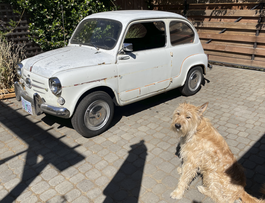
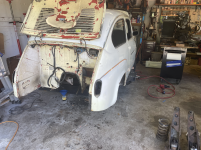
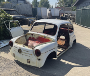
here is the car as bought:
1677188756264.png


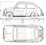
I bought the car in august 2022. Clearly my dog Marty is super excited about all the time i will be spending working on it, rather than going for walks. The car had spent alot of its life at the coast, so the rust is not ideal. This is my first body work project, so I dont expect it to be a show car. When i was planning this conversion, i carefully measured up where and how i could fit the (6) battery modules in the car. Most of the old Fiat conversion (mostly 500s in the UK it seems) use (3) tesla modules and place them under the bonnet and boot. The floors in this car need replacing, so i worked on a plan to place the batteries under the seats, just like modern EVs. It will keep the center of gravity low and give me space for other stuff up front and have storage in the back. Here is some cad exploration: You can see the battery module outline in orange.
1677188973641.png


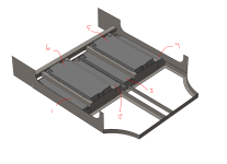
So, according to my rough CAD, i could fit 4 modules across the bottom of the car, and then one additional module under each front seat, between the seat rails. It will lower the floor of the car about 1.25in and raise the seat about 1in. The new seat rails will be on either side of modules 5 and 6. Like this:
1677189217454.png


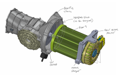
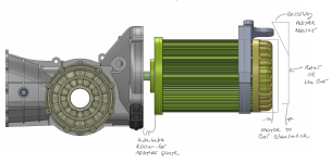
This will give me a voltage range of about 108-151V. The motor and motor controller i chose can support 90-180V, so its just right. Speaking of the motor, i made sure it will fit between the transmission and rear bumper panel. I also found a CAD model of a beetle transmission so i can work on new mounts and adapter plates. Here is how it is coming together:
1677189800457.png

Note the clearance to the back of the car and how i plan to use the existing motor mount to hang the back of the assembly from. I will also be working on getting the standard transmission mounts adapted to the car, but i am less concerned with that, at this point:
1677189865602.png


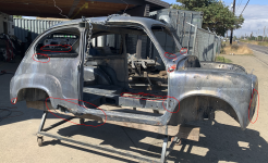
So, now that it doesnt seem totally CRAZY to fit all of this stuff in the car, I got to work taking the car apart, preparing it for a metal dip. Here are some progress pics of the tear down (note the car was originally red):
1677190398627.png


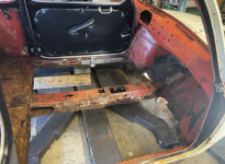
here you can see how rotted the floors were:
1677190464594.png


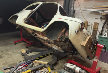
I also built a makeshift rotisserie out of harbor freight engine stands. I cant flip the car over completely, but i can rotate it 90deg either direction.
1677190555284.png


After completely stripping everything off of the car, it was time to haul it to the metal dip shop (in Eugene OR, totally awesome place):
1677190641567.png


When the car came back from the dip shop, i was heartbroken. i had a big decision to make... it was bad. Really bad. Should i scrap this car? I considered it. I would have to replace nearly everything. Even the doors were completely unsalvageable.
1677190955199.png


I had to source replacement doors. The only early (suicide) door i found on Ebay was 1000$. If i had to spent 2k$ on doors, this project was sunk. I decided that if i couldnt find reasonably priced doors, i was going to scrap it. Then i discovered Chris Obert down in Santa Cruz CA. He had 16 doors for me to choose from and sells them for 150$ ea. He was kind enough to take a video of each door, reviewing their health and let me choose. it was awesome. the project was back on!
While I wait for the spring spacers, I am getting after some details like the steering wheel and trim bits. I watched a great video on how to refinish a steering wheel and basically followed that process. First, clean it up and scrap out any loose junk in the broken plastic. Second, fill the gaps with a 2-part epoxy filler. Third, sand. Lastly, paint. Simple, right? Well... here are my progress pics.

After filling with the Oatey Fix-it-stick:
1712116233323.png


Sanded and ready for paint:
1712116281276.png

And after priming and painting:
1712116393007.png

I was excited how it turned out. Then I flipped it over. There is a reason i paid someone to paint my car... I seem to be bad at it. The clear coat can clearly said "2-3 light coats a few minutes apart". I swear I was doing light coats... but upon flipping the wheel over the next day... runs galore. Sheesh. I have some wet sanding and respraying in my future.
1712116559492.png

In better news, I cleaned up the badges and trim and started preparing them to put back on the car. I repainted the Abarth badge that came on the car and the Fiat emblem on the hood; they both looked tired. When I was doing body work on the car, I closed up all the trim holes in the doors and hood. I had planned to use molding tape instead. Then i saw @Bounding Bambino thread on using magnets to hold the trim on. I considered this but decided against it for fear of the magnets attracting debris and eventually messing up the paint. So, back to my original plan, which requires filling the inside of all the trim bits with epoxy so the tape has something to grab. I filled the hood trim, side trim and the nose trim. Here is a pic of the nose trim after filling the inside cavity with epoxy:
1712116917239.png

Then I put molding tape on it and stick it to the car. Easy-peasy. Here is how the nose turned out:
1712116982017.png

I think I am going to leave off the smaller trim bits above and below the mustache for now. I like how clean this looks.

And finally, here is the back:
1712117120744.png

Its really coming together!
 
Hello all... I have been zipping all over town in this little blue gem. It now has 199 miles on it and its a hoot. I have been shaking it down, working through issues and continuing to add finishing touches. With a few of those finishing touches, I now consider the outside of the car complete. I also have been working on interior bits, continuing to tune the brakes, brake pressure regen mapping, accelerator mapping, charging, etc... First up, the outside finishing touches, such as the mirrors, trim, and wheels/tires. As it goes on this project, the side view mirrors (specifically suicide door mirrors) did not fit on my doors. Why? no idea, but its a bummer. The door frame was too wide.
1713802775849.png

as you can see, the channel in the mirror is smaller than the frame. So, what to do? Well, I cut up the mirrors and drilled holes in the door frames to mount the mirrors. Not what I wanted to do, but I was desperate to get mirrors on the car, and not only for the cute factor, but also cuz I really use them!
1713802914398.png

I bolted them to the frame, but also put molding tape under them to keep water out. They are quite secure now, but unmovable, so I have to be ok with their position (which I am, though the passenger side requires I move my head to make use of it).

Next up is the belt line trim and the white walls. The trim is easy enough and just required some care in making sure it was in the right spot, that the car was properly cleaned for the tape, and pressing it into position. More controversially, I also added white wall stickers to the tires. I saw and have read that the snap-on style white walls suck, so I avoided them and went with the permanent style that gets applied with glue. The procedure is straightforward, but time consuming. In the end, I love them, but they took some getting used to...
1713803280153.png

I choose the size because of the tires on the car (Firestone F-560's). They have a radial feature outside of the firestone logos and tire info that seemed like a natural location to end the white wall. I did not expect them to be so bold. When they were first completed, I thought I had made a terrible mistake... but they have grown on me and more people like them than not (I have been taking a poll). So, I am fully embracing the silliness of them and really leaning into the toy-ness of this car. It has a backup bell after all, right? In the end, it may not matter much. I suspect i will be going through these tires quickly given the glorious acceleration in 1st gear. More on that later.

As for the interior, I added the convenience shelf under the dash, finished up the doors and center console. Then I got after the horn. Making a center horn button work with a removable steering wheel is not straight forward.

The doors needed plastic lining, as I had mentioned earlier. A tremendous amount of water gets into the doors, especially during a wash. I wanted to keep the door cards from getting soaked every time, and I really don't want a bunch of water getting into the car, especially given the battery locations. So, I lined the doors with plastic before using velcro to attach the door cards. Velcro? yes... it's an experiment that is working out so far. I did my best to make the plastic curtain complete, so all the water drains out the bottom of the door, through the drain holes. After washing it this weekend, I can attest it works:
1713803795653.png

and with the finished door cards:
1713803823825.png


Next up is the center console. I finally got all the aluminum knobs and sst fasteners to finish it out. I love it:
1713803901620.png

the seat heaters are fully functional, and are quite lovely. Those big wires are for them and I am not sure how best to hide them. In reality, they are not as noticeable as the picture suggests. You may also notice the carpet and center console vinyl. Both turned out nice:
1713804013077.png


The black wire and box thing is actually the GPS antenna for my speedometer driver. Under the dash, there is a box with a motor in it, designed specifically to drive old timey speedometers. One just runs a speedo cable from the box to the back of the speedometer, calibrate the box for your specific speedometer, and off you go. Its quiet and accurate. It has provisions for a GPS antenna (see above) or using a VSS (vehicle speed sensor). I have been working on getting a VSS sensor system in this car without success so far. More on that later.

The convenience shelf was easy enough. It consists of a wooden dowel (closet rod, actually) wrapped in vinyl. My awesome neighbor has an amazing woodshop, and he was kind enough to run a relief cut down the length of the dowel for the shelf on his amazeballs table saw. The ABS shelf I made slips right into the groove. Like this:
1713804323143.png

I added some left over carpet to it for extra luxury. I cut a relief in the shelf for the steering shaft and the future heater tube. I didn't even have to fasten them together. The cut was precise enough, it was a perfect press fit with the vinyl in place:
1713804426218.png

I also attempted to seal up the boot lid louvers. I did this with some left over weather stripping and a piece of ABS that attaches to the same bolts that hold on the license plate. So far it keeps water out only OK:
1713804531064.png

but the fiat now hauls groceries like a champ!
1713804571052.png

the finished trunk is certainly nice enough. I added a basket to the motor cover, so its at least somewhat useful, and I turned it into a "hood" of sorts so I can check to make sure the motor is still there:
1713804880772.png


The Fiat makes everyone smile. I am a bit weird in that I really feel like inanimate objects, like the wee fiat, have souls. This little fiat has been fighting me during this entire project. I feel it has finally started to relax and embrace the change. The corvair cooperated nicely during the entire EV conversion process. Maybe the fiat has finally learned a bit from its big brother.
1713805122604.png
 
Last edited:
Hey all. Our little fiat now has 250 miles on it and I am continuing to refine it. I got the horn to work with the removable steering wheel, and we aligned the car.

I was driving around without a horn for a bit, and I was surprised at how often I needed it. Mostly to beep back at folks excited to see the car, but also to let huge-ass pickup trucks know I was there. Also, the previous owner had 5 horns in the car. I do not know if he used all of them at once, or if he added one if they stopped working. Whatever the reason, I now had a variety to choose from. So, the whole fam gathered round to test our options and we decided on what I call the "Cadillac horn". It's a horn that has no business being on this tiny car and its very loud. All good, from my perspective. I had already plumbed wiring for it and got to work getting the steering wheel modified. The horn button on this car is the grounding type... meaning there is only one wire that has to pass through the rotating bits. The horns always have 12V on them, and the ground wire is what is switched through the relay. I think most cars are like this, actually. Its clever. The first step is to get a slip ring connector between the steering column and the steering shaft. I did this by harvesting the parts from the old steering hub assembly. I put the brass slip ring on the new hub and with some drilling, ran the wire out to the front. Like this:
1714948440984.png

the wire is connected to a sst flat head screw that will be located in the hole of the steering shaft:
1714948507058.png

I used a screw so I can adjust the distance, or the "throw" of the horn button. Here is right before assembly:
1714948607104.png

And with the sst flat head in position:
1714948655363.png

Now, on the steering wheel side, I needed some spring loaded button that will touch that sst screw and connect it to ground. I am assuming there the ground connection through the steering wheel connection is adequate. This required that I take the Fiat center button apart and re-organize it. I drilled a large hole in the back plate, epoxied in a nut to the actual button, and now I can add a bolt to reach down and touch the sst screw above. Like this:
1714948865236.png

Then I added the copper lug and spring that was inside the horn button to the bolt and there you have it!
1714948927596.png


I snap that back into the steering wheel and adjust the sst screw in the steering shaft to get the right travel. So far it has only gone off twice without me touching it. I suppose I will be adding more gap to it soon. We have a family legend about when years ago, on my 1977 Datsun, the horn button broke and activated the horn continuously.... for the entire drive home... with my 8yr old in the car. He was so embarrassed! I could have pulled the fuse, but it was just so funny.

Now... the alignment. As with most things on this project, getting an alignment was not easy. Why? Well... the damn car is too narrow to fit on a modern alignment rack! I called around to a few places, included my favorite local shop, but no dice. So now I get to learn how to align the car myself! I borrowed these fancy alignment thingies from a friend and started with the front. They look like this:
1714949308676.png

They are really clever. You set them up for the rims you've got, so they touch on the bead edge (not outer lip). The floor doesn't even have to be perfectly level. My friend says they use these at the racetrack to make quick adjustments during testing. Once you have them setup on both sides, you peer down this periscope looking thing and use some guide marks to determine the toe. The opposite side actually has a mirror, so when you adjust the dial to determine the toe, you only have to adjust the side you are looking through. So easy! I eye-balled the fronts a while back and wouldn't you know it? they were off... over 1.5deg of toe out.
1714949638347.png


Adjust the front is easy enough. Its a big trickier to center the steering wheel, which requires trial and error for me. So after a few adjustments and some driving to center the wheel, we now are aligned (toe only) and centered. It has the tiniest bit of toe. less than 0.5deg.

The rears are not easy. Maybe some seasoned Fiat owners know how to adjust the rears, but I dont. I know there are a bunch of shim-like washers at the rear swing arm pivots. I assumed they are for dialing in the alignment. When I first measured the rears, they had 1.5deg of toe-OUT. This explains why the car was hunting all over the place on the freeway. The back tires really wanted to steer the car. So, first, I climbed under the car and removed all the shim washers (which I installed in a somewhat random way, just what was easy). I now biased them all to the outside, in an attempt to pivot the wheel in, adding toe-in. It did nothing at all. My measurements before and after were the same. I had to CAD up a shim to put under the bearing block. Some quick math said I could order 0.02in sst shim stock, and each shim would adjust the wheel less than 0.5deg. I ordered 4 from oshcut.com and they arrived in short order. I figured I would need to add 3 or 4.
1714950183885.png


And when they are slipped into the back half of the bearing block, they should rotate the rim and add more toe-in. It looks like this:
1714950266362.png

I added two the right and one to the left and now have just under 0.5deg of toe-in in the back. Perfect. I decided on adding a bit of toe-in in the back because I think this is the more stable setup. Any toe-out is bad news, so better to error on the safe side.
1714950508994.png

A keen eye may notice that the dial reads nearly 30min OUT... thats because its opposite when these are used on the rears.

Now this alignment does not check for camber, caster and the other more refined adjustments. Nor does it check for "jacking"... where the front and back wheels are not aligned with each other, and the car appears to drive crooked down the road. I will likely adjust camber when I can borrow an inclinometer and spend the time leveling the car. Then I get to adjust the toe again... its a fun game. I will also probably drive behind my gal while she drives the fiat to make sure the car doesn't look too crooked and call it good.

In other news, the gas gauge is working well enough to do a range test. Now that its aligned and I have a horn, and when it stops raining, I will do that. I did put 100 miles on a charge last week and still had 35% left, and this was with a bunch of burnouts all over the place. So fun.

Next up is the center dash plate and the A/C and heater.
 
Installing the A/C unit was a serious pain. This is probably the least serviceable part of the build so far. It looks at home once it's in. And now that its in, i can finally test my hair-driver cabin heater. If you'll remember... I pulled a heater element out of a 1800W hair dryer to be my cabin heater. My pack voltage is 150V-ish DC and the house voltage in the USA is 120V AC... close enough! I just hook connect that heater element directly to my traction battery pack with a contactor, and off we go. Here is the A/C unit:
1714951379771.png

The position of the "out" is unfortunate, since i have to route a rather long tube down and to the big hold I drilled in the car, right at the top of the center console. That is the location of the heater element. Upon turning on the blower, it moves plenty of air (phew!). Is it enough for the heater element? Let's see... if it's not enough, the heater element will overheat and trigger its safety switch. This is NOT a PTC heater... meaning the resistance of the heater does not go up with temp. Those are the best heaters for this application. They are also bigger, and I don't have the space. So, let's see if this 25$ hair dryer works, shall we? Here is a pic looking down the vent tube, inside the car:
1714951641823.png

It works! works so well, in fact, that the cabin was WAY too hot after about 3 minutes. This heater is too big. And it gets way too hot. The air flow over it is barely enough to keep the element from getting too hot and the tube and surrounding stuff was getting quite toasty. What to do? I had two options:
1. Get a timer thing that will basically PWM the heater, using the high voltage contactor that connects the heater to the traction battery pack.
2. Get a lower wattage hair dryer element.

The problem with option 1 is that the HV contactors are expensive and not designed to toggle constantly. They have a life of 1,000,000 cycles (mechanically, likely less electrically). I guessed I would have it on 50% of the time... the math said I would have 800hrs of heating, max. That could last a few years, but not long enough before buying an expensive replacement contactor.

The problem with option 2 is that it's hard to find lower wattage hair dryers that have an element that will fit gracefully in the space I have allocated.

I ordered parts for both. I found a 1000W hair dryer. If there was a competition for the cutest hair dryer, I am pretty sure this little guy would win.
1714952035606.png

But... does the heater element fit? turns out, YES. thank goodness. With some trimming and add screws, I got the element to fit into the exact same housing of the 1800W heater.
1714952146922.png

and it fits well:
1714952181948.png

I can say it's just about perfect. I ran it for about 10 minutes and the cabin was nice and warm (it was about 49F in the garage). It also looks way more reasonable... not nearly as hot:
1714952320805.png

I have it wired so that if the fan is turned off, the heater is also turned off. In other words, the heater can't be on if the fan isn't on. Same for the A/C.

For the super cold days, I also have seat heaters. I feel like we will be comfortable with these options.

The A/C system is working, but it's been too cold to tell how well it works. We are supposed to get some 80F days soon... hooray!

Next up... finish the HVAC plumbing and start on the splash panels and rear diffuser under the car. I am a lucky guy!
 
A while back, I had planned to make a vent panel to mount in the center under the dash. I CAD'd up my final design and had it made at oshcut.com. I love that place. It showed up with some rather deep press-brake tool marks for the bends. I should have anticipated this, but didnt. So, i had to sand a bunch and then re-apply the brushed finish. Here is how the finish turned out... if you look closely, you can still see a faint tool line towards the bottom:
1714967145211.png


I installed the clock, two vents, a cigarette lighter (i dont smoke, i just thought it was appropriate) and the washer fluid pump. It mounts under the dash pad, and above the convenience shelf like this:
1714967249363.png


after getting it installed, i learned two things. The clock, that came with the car, is a Veglia, and i was super duper excited to use, just doesnt work. It kind of works, but after an hour or so, it just stops. I tested it on the bench, but not long enough, it seems. I had run a direct, fused line from the battery so it would always be accurate... except when it randomly decides to stop. So, that is lame. The second thing is that it breaks up the simplicity of the convenience shelf and doesn't seem to fit the dash vibe I had in mind. It is becoming too airplane-ish. I decided to take it out. This means that the HVAC system will switch between defrost and feet. I think this is better for cold weather, but worse for hot weather, since the A/C wont be aimed directly on me. If its unbearable, i can add this thing back in. The wiring is all there. They even sell reproduction clocks in the US. In the meantime, I will mount the washer pump to the left of the steering wheel on a bracket i have yet to make.

This decision meant i could get the HVAC plumbing setup. So, now there are two vents that aim down towards feet, and two that connect to the windshield defrosters. Its all black, so its not easy to see without looking for it:
1714967847815.png

One of the silver levers will eventually control which direction the air goes. I have yet to get the cabling to do that.

Now the car has the first pass at working heat, A/C and defrosting ability. I will use it for a while and see if its good enough. We will see!
 
Back
Top