No rain here in Norfolk and it’s still 23’C at the moment here


You are using an out of date browser. It may not display this or other websites correctly.
You should upgrade or use an alternative browser.
You should upgrade or use an alternative browser.
Currently reading:
What's made you grumpy today?
No rain here in Norfolk and it’s still 23’C at the moment here
Only 23!
I'm on my way.
32 here. For the last three days. Horrid
That’s right now at 9pm, it was 36 in the car when I was driving home from work
That’s right now at 9pm, it was 36 in the car when I was driving home from work
Was similar in Oxford area.. 35/36
Was 32 at our house..halfway up a mountain
(not a Norfolk thing.. )
")
Was near Bedford today and the rain was very, very intense as well as lots of thunder and lightening.
Some German cars seem to be equipped with radar as well as rudders, given their speed through the rain.
Some German cars seem to be equipped with radar as well as rudders, given their speed through the rain.
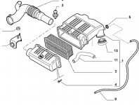
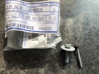
Seems like eper isn't showing me the right part. I looked at the list for the screws and it shows part number 4. So I ordered 6 to replace the rusty ones on mine. But no; what did I get? 6 set screws that are used to hold down the main air filter body to the engine.
My local dealer says they cannot help as their version shows the same.
I have now written to Fiat to see if I can get an answer.
My local dealer says they cannot help as their version shows the same.
I have now written to Fiat to see if I can get an answer.
Attachments
Just one of those things..right?

Who could have pre...oh

Pesky mot man trying to stop you killing yourself and others...
Who could have pre...oh
Pesky mot man trying to stop you killing yourself and others...
And I heard Japanese cars were reliable
And I heard Japanese cars were reliable
The thing with "reliable" cars is...they attract people who have no interest in actively looking after them.
Yesterday there were a number of extreme down pours of rain, Driving home from work last night there was a lot of flooding including the middle of major A roads, there was a car about 5 miles out of norwich that had been in an accident with probably an animal and was awaiting recovery, there was another broken down in a puddle, and about half way home there was a 62 plate Punto (2012+) that had clearly gone into a truck bead or similar being recovered with a huge hole in the front wing that turned into a massive gash down the wing and drivers side door peeing all the bodywork off as it went the tyre had also been nearly removed and it was being unceremoniously dragged onto a flat bed truck, which is a shame as it looked like a clean car but sadly there is no way they would do anything but right it off.
My oldest boy is not a technical or DIY person - but Oh man, can he play guitar! So "Granddad" gets to fix most of their stuff. About a week ago he dropped off his Flymo strimmer - Contour 650E - which had just suddenly stopped working. He'd been using it and it was going just fine, then the next time he pulled the trigger, moments later, nothing happening! No slowing down or erratic operation and no smoke or burning smells, just working one moment then not working at all! He tried a new fuse but that made no difference.
I was really quite looking forward to sorting it. The strimmers I've had in pieces before were pretty simple devices. I couldn't find anything on you tube about stripping it down so, after checking the fuse "just to be sure", started taking the motor end to pieces first - my thinking being I can check out the motor for stuff like seized brushes etc and also check continuity on the wires from the handle mounted switch trigger.
Splitting the case took me a moment or two (best part of an hour actually) because once all the screws are out you have to jiggle about with the spring loaded angle locking lever to disengage it from it's toothed internal rack! I stopped at that as it was evening and luckily found a parts diagram for it online that evening. This helped a lot but also revealed complications.
Turns out it's nothing like as simple as previous ones I've worked on. The power supply comes in through the handle to a microswitch in the handle (parts diagram calls it a microswitch) - I'm always a bit suspicious of microswitches used for "rugged" machinery which is likely to be abused. I still haven't figured out how to split the handle to gain access to this switch but testing the wire at the motor end for continuity when the trigger is pulled shows the switch to be working and current reaching the two wire ends, so maybe I don't need to get inside the handle?
I've had a very close look at the motor and done some basic investigating using my multimeter and it seems Ok but I'm not an electronics engineer so there is room for doubt. Interestingly the two wires from the microswitch in the handle feed the mains current to a PCB which has quite a bit of componentry on it and then two wires come from the PCB to the motor. My "educated guess" is that something on the PCB is scuppered and I can't check or sort at that individual component level. Current is present at the PCB input when the handle switch is pulled but none is seen at the PCB output terminals.
So the "cure" is probably that it needs a new PCB - around £20 so about a third of the price he paid for the whole machine over 5 years ago. Trouble is that although I think the motor is Ok I'm not absolutely 100% sure so do I risk his £20 on a PCB which might just be ruined the first time the trigger is pulled or do we call it a day and buy a bargain basement Aldi/Lidl replacement?
I've been trying to figure out what the PCB circuitry is actually doing. The motor runs at one speed only so it's not to give variable speed. I immediately wondered if it was acting in the same way as a relay to "save" the microswitch but I don't think that can be the case as all the current passes through the microswitch before going into the PCB.
Why does such a simple device need to have a PCB anyway? Surely all you need is a motor and a switch - like the others I've had in pieces? Ah well, I think I feel an Aldi/Lidl shopping trip is in the offing. Feeling grumpy because i can't fix it!
If you DM me a picture of the board jock or post it here (front and back) I can take a look and see if there is anything obvious on the board like a blown or bulging cap, or advise maybe what the board does, if it’s a 250v Motor in the strimmer you may be able to completely do away with the board and connect it directly I know some people have done this with drills sometimes the board might be there to protect against high current draw or over heating?
- Joined
- Mar 1, 2014
- Messages
- 4,432
- Points
- 828
I'm getting absolutely sick to the back teeth of hearing the snowflake generation whining on about their a-level results. Don't get me wrong: it's not nice to have plans cocked up when it isn't your fault, but in the grand scheme of things, they could have it far, far worse...
If you DM me a picture of the board jock or post it here (front and back) I can take a look and see if there is anything obvious on the board like a blown or bulging cap, or advise maybe what the board does, if it’s a 250v Motor in the strimmer you may be able to completely do away with the board and connect it directly I know some people have done this with drills sometimes the board might be there to protect against high current draw or over heating?
Thanks Andy. I've no idea what a "DM" is so I'll just send you the pictures here and hope you get them.


Looking at the terminal block in the second picture the second from the left (blue) wire and fourth from the left (brown) wire are from the microswitch in the handle. The other two wires are to the motor.
I'd be very interested to know what it's doing so I hope you may have some idea.
Thanks again for having a go at this
Kindest regards
Jock
Just taken a very careful look at the motor and there is no labeling which might indicate as to what voltage it runs. However if you follow the blue feed wire from the PCB it connects to one of the two field windings. having traveled all around that it goes to one of the two brushes, round the armature windings via the commutator and then through the other brush into the second field winding and finally connects to the brown wire from the PCB. So, my uneducated guess would be that it's a 240 volt motor otherwise the PCB components would be more massive to cope with current?Thanks Andy. I've no idea what a "DM" is so I'll just send you the pictures here and hope you get them.
View attachment 211890
View attachment 211891
Looking at the terminal block in the second picture the second from the left (blue) wire and fourth from the left (brown) wire are from the microswitch in the handle. The other two wires are to the motor.
I'd be very interested to know what it's doing so I hope you may have some idea.
Thanks again for having a go at this
Kindest regards
Jock
Or, hang on, Commutator did i just say? doesn't that imply a DC motor? Getting out of my depth here.
Here's detail of the field coil and it's wiring on the "brown" wire side. The other field pole is identical, just with a blue wire in place of the brown

Thanks Andy. I've no idea what a "DM" is so I'll just send you the pictures here and hope you get them.
View attachment 211890
View attachment 211891
Looking at the terminal block in the second picture the second from the left (blue) wire and fourth from the left (brown) wire are from the microswitch in the handle. The other two wires are to the motor.
I'd be very interested to know what it's doing so I hope you may have some idea.
Thanks again for having a go at this
Kindest regards
Jock
Nothing looks to be obviously burnt out but apparently that big yellow capacitor in the middle of the board is known to fail when used
I'm getting absolutely sick to the back teeth of hearing the snowflake generation whining on about their a-level results. Don't get me wrong: it's not nice to have plans cocked up when it isn't your fault, but in the grand scheme of things, they could have it far, far worse...
I agree fully. I mean, it’s not like the government and the world has had anything more important to focus on this past six months [emoji849]
Plus, whatever went wrong, it can be resolved. No need to riot on the streets.
I honestly fear the day our generation is fully controlling the ropes. At least in my job we’ve still got managers my parents age and older who adhere to the rules, but can low key roll their eyes at some of the crap we have to adhere to these days.
- Joined
- Mar 1, 2014
- Messages
- 4,432
- Points
- 828
Like yourself, I honestly dread the day that the InstaTwit generation take power. It really doesn't bear thinking about! [emoji33][emoji33]I agree fully. I mean, it’s not like the government and the world has had anything more important to focus on this past six months [emoji849]
Plus, whatever went wrong, it can be resolved. No need to riot on the streets.
I honestly fear the day our generation is fully controlling the ropes. At least in my job we’ve still got managers my parents age and older who adhere to the rules, but can low key roll their eyes at some of the crap we have to adhere to these days.
Like yourself, I honestly dread the day that the InstaTwit generation take power. It really doesn't bear thinking about! [emoji33][emoji33]
I can only hope that while the far left are out rioting and making their big scenes online ... that the level headed and intelligent side of the younger generation is actually out there working their way up and actually trying to improve the world without pointing fingers at everyone but themselves..
- Joined
- Sep 14, 2009
- Messages
- 19,947
- Points
- 3,966
Hi Jack.
Until recently, those commutator motors are used in all sorts of power tools. The latest have brushless motors - cheaper (these days) to make and more powerful, but totally useless without the electronics board.
Any commutator motor can be made to work on a.c. or d.c. These have a laminated rotor and stator so the a.c. current does not cause inductive heating. They run because the a.c. power causes the field and rotor polarity change at the same time. Induction motors are better but wont spin so fast and single phase have poor starting torque.
Last edited:
Similar threads
- Replies
- 28
- Views
- 1K