Technical unknown electrical connector

Currently reading:
Technical unknown electrical connector

Status
Not open for further replies.
Joined
May 30, 2023
Messages
9
Points
3
Location
lincolnshire
hi all my first post so hopefully someone can advise me

i am trying to connect a reversing camera to my fiat panda 2007, I have threaded the wire from the head unit to the boot and made a bracket to fit the camera to, now all i have to do is to wire it up!
researching your forum it appears that i need to connect into the grey wire going to the rear light cluster?
however when poking the wire up into the boot i noticed this strange electrical connector hidden behind the rear bumper!

20230516_151011.jpg


does anyone know what it may be used for?
I was thinking that it may be a factory fitted connector for a towing bar?
if so can i use this grey wire ?
will it be connected to the reversing light"!
 
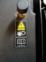
On the subject of voltage I thought I'd post this. It's a warning sticker on my Merc which has intelligent lighting system. How is this voltage achieved. With my limited knowledge on auto electrics apart from the engine I can only assume it's similar to how an ignition coil works.
I have posted on the MB forum but not received an answer yet.
 

Attachments

  • 20230825_105901.jpg
    20230825_105901.jpg
    1.6 MB · Views: 33
Last edited:
On the subject of voltage I thought I'd post this. It's a warning sticker on my Merc which has intelligent lighting system. How is this voltage achieved. With my limited knowledge on auto electrics apart from the engine I can only assume it's similar to how an ignition coil works.
I have posted on the MB forum but not received an answer yet.
I presume this is the ballast on a HID headlight? There are several ways to get very high voltages from a lower voltage but as the voltage goes up the current goes down,

This why electric fences are able to produce 10,000+ volts but not kill the animal that touches it.

In your case that module would probably give you a nasty jolt but not kill (unless you had a known heart conduction problem or a pacemaker fitted)

You can look up charge pumps, voltage boosters, some methods involve creating an AC current, boosting that and then converting it back to DC, but in this case I can’t say specifically what they have used
 
On the subject of voltage I thought I'd post this. It's a warning sticker on my Merc which has intelligent lighting system. How is this voltage achieved. With my limited knowledge on auto electrics apart from the engine I can only assume it's similar to how an ignition coil works.
I have posted on the MB forum but not received an answer yet.
Xenon Headlight Warning Sticker for R129, R170, and W208 possibly others as @AndyRKett said
 
I just want to say

GRRRRRR to add somthing friendly!

i dont know whos right but Ive never had a soldered wire cause me a problem. Its clear plenty of care is best. Oldcars ARE better than new ones. Ols is best in allthings.
 
I presume this is the ballast on a HID headlight? There are several ways to get very high voltages from a lower voltage but as the voltage goes up the current goes down,

This why electric fences are able to produce 10,000+ volts but not kill the animal that touches it.

In your case that module would probably give you a nasty jolt but not kill (unless you had a known heart conduction problem or a pacemaker fitted)

You can look up charge pumps, voltage boosters, some methods involve creating an AC current, boosting that and then converting it back to DC, but in this case I can’t say specifically what they have used
Well that's good to know. I thought 25000v or even less than that would fry you. Like I've said I'm not very clued up with electrickery.
Having said that I've had a few belts over the years off plug leads which carry high voltages with no ill effect.
 
Last edited:
DC is much much much safer then AC
The oposite was much as well proven in the argument between Nicola Tesla and Thomas Edison... but I am not going to get into it here. Simply, DC gives the power/strenght, AC allows the transmission. Even matching voltage and current with AC and DC, DC is constant while AC is in waves.
 
Well that's good to know. I thought 25000v or even less than that would fry you. Like I've said I'm not very clued up with electrickery.
Having said that I've had a few belts over the years off plug leads which carry high voltages with no ill effect.
In simple terms, it is not the voltage (amount of units*) that can harm, it is the current (strength of each unit*). A domestic / comercial wiring is protected by at least 20 fuses / sensor circuit breakers in a circuit and limited to normally 40 amp range. A car battery will put out up to 200 amps at peak.... which can burn through human skin into the wiring in the body (nerves etc) and across the heart / brain (though for some of the people posting here, it might be years before that is noticed). The voltages / currents within the body are in the range of 1-2 micro volts and 1-2 milliamps. As a result, if the voltage/current raises in the body via an electric shock, each muscle contracts to such force to break bones and rip muscles from the bones. Even if you survived the shock, your bones would be burnt / in powder.

Electric transmission use huge voltages or similiar to be able to drop the current and the loss in the cable and to make it realitively safe. Car voltages are within the 11-15v range, but have currents much higher then in domestic / comercial.

All I keep saying is, don't assume that the car circuits are safer than your house. They are not.

*simplified explaination
 
I presume this is the ballast on a HID headlight? There are several ways to get very high voltages from a lower voltage but as the voltage goes up the current goes down,

This why electric fences are able to produce 10,000+ volts but not kill the animal that touches it.

In your case that module would probably give you a nasty jolt but not kill (unless you had a known heart conduction problem or a pacemaker fitted)

You can look up charge pumps, voltage boosters, some methods involve creating an AC current, boosting that and then converting it back to DC, but in this case I can’t say specifically what they have used
HID are a variation of arc lights where the driver circuit is made up of a choke / coil and a capacitor as a form of voltage multiplier. This creates the high enough vltages to create a sustainable arc across the electrodes in the lamp. It is not the high voltage that is the danger in these, it is the discharge capacity of the capacitor that is in circuit. The same type of circuits exist in a microwave that creates the very high voltage low current to drive the magnetron and in the old CRT televisions that create the high voltage low current spark the length of the tube for the spark to hit the screen and energise the relevant phosphorous dot.

Again, there are saftey circuits in all these devices, but these can fail which can lead to high discharge currents on a car system if someone is playing around with something that they think they know.

There was and TV program '1,000 ways to die', and I'd prefer no member here became a feature on same. We all laugh at the stupidity of these people, but an accident takes more that one thing to occur, and when investigated, it is usually operator error following a fault presuming that they knew what they were doing OR doing omething that they had done multiple times before.

There are very few old domestic / comercial electrictians still 'on tools', as they are now too scared to touch wiring after too many shocks.
 
I bought my first house 45 years ago. On mive in day I decided to wire in tge cooker. Duly opened the fuse box and removed the biggest fuse.
It was a shame it was not the right one. Its a good thing I was wearing rubber soled shoes that day. It disd blow me across tge kitchen. Wife was disappointed not to get the life insurance. She's still browned off about that today.
It does prove that taking care and not overstepping your skill level is important.
 
I think this thread has more than run its course.

It’s not good to start making unnecessary snarky comments.

The original thread was about finding a wire for a reversing camera, which has been answered, now it’s just all getting a bit silly
I agree. What you write is always open to interpretation and can be offensive even if none was intended. I was always upsetting people at work....
Healthy discussion is good, as are differences of opinion as this can be thought provoking. Its not good when we get carried away. I would like to see people make references to sources of their info rather than getting pointy. This either confirms the facts or improves discussion. There is a lot I can learn on this subject even if it was wildly away from the original whats this plug.
 
I bought my first house 45 years ago. On mive in day I decided to wire in tge cooker. Duly opened the fuse box and removed the biggest fuse.
It was a shame it was not the right one. Its a good thing I was wearing rubber soled shoes that day. It disd blow me across tge kitchen. Wife was disappointed not to get the life insurance. She's still browned off about that today.
It does prove that taking care and not overstepping your skill level is important.
I'm glad that your still alive, but does metal items stick to you and bulbs light if you put them in your mouth (similar to Fester Adams)? Don't mention this to your wife, but has it effected your brain ability?

Re original topic... with car electronics, don't assume that a lower voltage is safe... as there are times that it will not be... and at those times, it is either very expensive (ECU / body computer / air bags etc...) or worse, lethal. If you wish to probe a car with a multimeter, make sure that it is of good quality and meets / exceeds requirements as @AndyRKett has identified being from Fluke, since you are trusting your life with it. Most meters sold in motor factors / DIY stores, due to 'electrical bits' being an added extra to the stock items, are really not safe. One of the worst items to use on car electronics is the bulb on a wire devices (brass rod with a bulb in it plus a trailing wire) as it connects you to one side of the circuit and/or partially grounds digital signals. Hopefully, the computer that you partially ground can survive that, and if it doesn't (it is not guarenteed to do as car makers really don't want people playing around with the electronics) all the expense and hassle is replacing the relevant computer. Yes, they can be repaired but most of the service manuals in relation to the computers are protected by the relevant maker. Otherwise, they would not make the extra money for adding an alarm etc. Yes, the Fiat body computer (that has central locking) has all the relevant circuits and ICs to act as a car alarm but the programming has not been added.

reversing light.jpg


The Haynes car manual identifies the colour of the wires on the rear cluster (18) for each bulb circuit. The reverse light (a) is powered by the white cable (Bianco) and the black (Nero) wire as ground connected to pin 3, but since the other end is connected to pin 1 connecter F directly to the body computer (7), it is still not advisable to directly connect this to an external device like a camera without at least sone interface / protection between them. After all, the camera will be outside the car and in the event of a rear end collision, could be squashed. This has the possibility to short the reverse signal to ground, and you would be left with no reverse lights, or even worse, half or more of the lights unable to work. This is not only dangerous, but illegal to drive the car that way.

Warning - Car wiring colours, over itterations change so your model may be different that this diagram.
 
but has it effected your brain ability?
I don't know, cant remember, but this could be old age and bang on time senility. I thought the light in my rear end was the sun but it seems Im wrong on this too...
I now always switch teh whole house off. I dont trust that either and have a live wire tester (Draper) which seems reliable and I use an electrical testing screw driver as well as switching off all the breakers too. My multi meter is probably of the cheap type you mention it has hard plastic contact handles, but I wouldnt use it on anything live. I shall treat the car can bus with a little more respect from now on, on the basis its better than regretting not doing so in the queue at the bank to get the cash out....
I have done plenty on car wiring with and withour can bus, but always basic stuff like wiring towbars. Reverse sensors is on my list of wants as I get older as its more difficult to turn round. I have relied almost totally on mirrors for the last 20 years and think sensors woudl be a sensible addition or a camera. I would use the towing supply to power that which should get around any can bus issues as thats already bypassed. I cant get my head around the apparent lack of voltage everywhere with this new wiring. Wizzardry. The old fashioned electrics were simple an dif you did it right and fused it you do anything. Again I learned the hard way by not being thorough and having my then young wife telling me the car had been on fire under the dash on a fairly ong drive home from work, though I do blame the cars wiring too as it was the choke warning light that had actually caused the short circuit. I now fit fuses at both ends of any wires I add, and use the ones with little LEDs that indicate failure. One of the best new (?) things I have come across. There is nothing like it if the towing wiring plays up in the rain and the dark,
 
Last edited:
Warning - Car wiring colours, over itterations change so your model may be different that this diagram
In my car there is no clour continuity in the rear lights. The air was well past blue by the time I worked out it was Fiats wiring and not mine that was causing issues when fitting the towbar wiring.
 
Most meters sold in motor factors / DIY stores, due to 'electrical bits' being an added extra to the stock items, are really not safe.
I'm going to go out on a limb here and say that most meters sold in motorfactors assuming the conform to british safety standards and haven't just been brought in cheep from wish.com are in all likelihood perfectly adequate and safe for most DIYers. I'm not going to buy a Fluke Meter, they're all made in China anyway and so it makes no odds to me to buy a cheapy from Mablin (which is the one I tend to use on cars) when at most all I want to do is check I have 12V, Can't remember the last time I checked a resistance on a car, or measured current (use a clamp meter for current)

the computer that you partially ground can survive that, and if it doesn't (it is not guarenteed to do as car makers really don't want people playing around with the electronics) all the expense and hassle is replacing the relevant computer. Yes, they can be repaired but most of the service manuals in relation to the computers are protected by the relevant maker. Otherwise, they would not make the extra money for adding an alarm etc. Yes, the Fiat body computer (that has central locking) has all the relevant circuits and ICs to act as a car alarm but the programming has not been added.
So I'm going to point out the glaringly obvious in your diagram.
rearlight.JPG

Short of sending high voltages down the reverse light wires you are not going to cause damage to the BCM because as far as the lights are concerned they are all electrically isolated from any logic or sensing circuits. Draw too much current and you might get an erroneous blown bulb warning but thats about the worst of it.

Bare in mind when the ground wire to the car body is bad and you put the reverse lights that ground wire is common with all the other lights on the back of the car, usually resulting in a reverse current back down into the BCM and to the ground in the sensing circuit or finds another ground via another bulb somewhere, but this does not usually result in any major issues, just clean the ground up and everything works as it should.


it is still not advisable to directly connect this to an external device like a camera without at least sone interface / protection between them. After all, the camera will be outside the car and in the event of a rear end collision, could be squashed. This has the possibility to short the reverse signal to ground, and you would be left with no reverse lights, or even worse, half or more of the lights unable to work. This is not only dangerous, but illegal to drive the car that way.
The lights are on the back of the car and in the event of a rear end collision could be squashed, with the possibility of shorting the reverse signal to ground (though if this were an issue it would imply you reversed into them) if its been a shunt bad enough to short wires to ground then I suspect a working reverse light is the least of your worries at that point. Worst case Fuse 31 goes pop.
 
I'm going to go out on a limb here and say that most meters sold in motorfactors assuming the conform to british safety standards and haven't just been brought in cheep from wish.com are in all likelihood perfectly adequate and safe for most DIYers. I'm not going to buy a Fluke Meter, they're all made in China anyway and so it makes no odds to me to buy a cheapy from Mablin (which is the one I tend to use on cars) when at most all I want to do is check I have 12V, Can't remember the last time I checked a resistance on a car, or measured current (use a clamp meter for current)


So I'm going to point out the glaringly obvious in your diagram.
View attachment 428719
Short of sending high voltages down the reverse light wires you are not going to cause damage to the BCM because as far as the lights are concerned they are all electrically isolated from any logic or sensing circuits. Draw too much current and you might get an erroneous blown bulb warning but thats about the worst of it.

Bare in mind when the ground wire to the car body is bad and you put the reverse lights that ground wire is common with all the other lights on the back of the car, usually resulting in a reverse current back down into the BCM and to the ground in the sensing circuit or finds another ground via another bulb somewhere, but this does not usually result in any major issues, just clean the ground up and everything works as it should.


The lights are on the back of the car and in the event of a rear end collision could be squashed, with the possibility of shorting the reverse signal to ground (though if this were an issue it would imply you reversed into them) if its been a shunt bad enough to short wires to ground then I suspect a working reverse light is the least of your worries at that point. Worst case Fuse 31 goes pop.

It is not MY diagram, it is from a Haynes Manual, as I already stated.

A clamp meter measures AC current, not DC current so it will not work on a car to measure current. I presumed, foolish me, that you knew how to use a meter!

Is it just me, or can you not see that item 7 includes up to the dotted lines outside the blue. The visible link between C1 and B1 are internal to (7), not a direct shunt as is the connections between L7 and C9. As a result, the positive line from F31 goes through two circuits within the body computer, not bypassing them as you assume. Haynes, in their imagery, use both the dotted lines (as the outside of a module) plus the transistor symbol to signify that it is computer controlled.

Just for you. I foolishly assumed that you knew how to read a circuit / wiring diagram.
key.jpg


Now, something that you are ignoring is that most reversing cameras are plastic, mounted outside in the rain etc, usually proud of the rear of the car, and are usually not IP rated. They can be the first item damaged in a crash - i.e. reversing into a wall / pole presuming the image is further away than it actually is. Home installed cameras are not usually scaled similar to factory fitted ones.

As a result, water will eventually enter same. Water is electroconductive and one of the elements required for rust. Connecting direct onto a car wiring without isolation means that eventually, water will short the circuit out to cause the reverse light to fail. What else it brings down due to the circuit being sensed by (7) is anybodies guess, but it is guarenteed to be a light circuit. Elecrical problems in a car usually occur at the worst time - when you are away from home / on holidays / raining / dark etc., and this will bring down light circuits. As a result, ignoring it and saying it won't happen is designing yourself to be in a situation without lights in the dark and rain - and to me that is idiotic.

bodypc.jpg

Here is another version of circuit diagram including the body computer (7) identifying L7 as a connection (similar to my prior post) but this time it is not connected to pin C9. Also, pin C6 doesn't seem to be connected to anything in the body computer! Also, this identifies I35 and I36 as the can bus of the body computer, where the arrows indicate the signals are being sent from the body computer and not to it.

One cannot assume that a link within a box is a direct shunt as it could be via an unlisted component.
 
Last edited:
Clamp meters can't measure DC current?


Best tell fluke they are wrong then
 
It is not MY diagram, it is from a Haynes Manual, as I already stated.
it’s “your’ diagram in that you posted it.

A clamp meter measures AC current, not DC current so it will not work on a car to measure current. I presumed, foolish me, that you knew how to use a meter!
Now you see you keep posting things that make me think you know nothing about electronics at all. Even some really cheap clamps off amazon and ebay will measure DC amps

The Irony here being I used to work Largely between the 8800 bench meter 9100 calibrators and literally dozens of products in the Clamp meter division, We made custom Clamps for the automotive industry that would be used in testing cars electrical systems while it was moving down the production line, including the first clamp meter to use Bluetooth to talk to the computers that ran The production line. We used technologies you’d get in any commercially available clamp.

Is it just me, or can you not see that item 7 includes up to the dotted lines outside the blue. The visible link between C1 and B1 are internal to (7), not a direct shunt as is the connections between L7 and C9. As a result, the positive line from F31 goes through two circuits within the body computer, not bypassing them as you assume. Haynes, in their imagery, use both the dotted lines (as the outside of a module) plus the transistor symbol to signify that it is computer controlled.

Just for you. I foolishly assumed that you knew how to read a circuit / wiring diagram.

This isn’t a circuit diagram, its a rough representation of the circuits in the system, Haynes do not do proper circuit diagrams they do simplified diagrams for DIYers.

The dotterel line represents the body computer, where i have highlighted, shows that internally the measuring circuits that check for a failed bulb are internally isolated. All that shows is there is an internal connection to the computer but it’s not showing the circuits in that computer. The line I have drawn shows the power for the reverse light goes in and then straight back out again, I am not sure how else you thing this would be achieved ?

Now, something that you are ignoring is that most reversing cameras are plastic, mounted outside in the rain etc, usually proud of the rear of the car, and are usually not IP rated. They can be the first item damaged in a crash - i.e. reversing into a wall / pole presuming the image is further away than it actually is. Home installed cameras are not usually scaled similar to factory fitted ones.
So what ?? In this case the wire in question was passing through a grommet behind the bumper and open to the elements and uncapped.
Any minor bump to the back of the car, or any water up behind the bumper or corrosion it was/is likely to be just as vulnerable.

If someone puts a cheap camera on their car and powers the actual camera from the reverse light rather than just using it as a signal, and it causes problems with there reverse light, because they reverse into a wall or park it in a lake, then fuse 31 will blow and that’s very much there issue.


Water is electroconductive
yet again saying things that make me question you know what you’re talking about. ions are electrically conductive. Water is an insulator.

and to me that is idiotic.
Then you can feel free to not install a reverse camera on your car.


View attachment 428738
Here is another version of circuit diagram including the body computer (7) identifying L7 as a connection (similar to my prior post) but this time it is not connected to pin C9. Also, pin C6 doesn't seem to be connected to anything in the body computer! Also, this identifies I35 and I36 as the can bus of the body computer, where the arrows indicate the signals are being sent from the body computer and not to it.

One cannot assume that a link within a box is a direct shunt as it could be via an unlisted component.
No idea what you’re trying to show here? As stated above haynes makes diagrams that represent the way things are laid out but are not an accurate circuit diagram showing all the components within that module or computer. The fact that this diagram differs from the previous one should be enough to tell you that they are not consistently accurate drawings?

At this stage you’re just arguing for the sake of arguing, trying to dig yourself out of a hole, and in doing so you keep highlighting that you don’t seem to know all that much about electronics, and turn to personal insults when you run out of structured argument.

I quoted you way back, where you said something about putting 10M ohm on your body computer and seeing how long it lasts, this shows you fundamentally don’t understand Ohms law. You don’t know that clamp meters can measure DC amps, you think that a Haynes diagram is an accurate representation of the inner workings of a body computer. I’d probably give up now if i were you.
 
Status
Not open for further replies.
Back
Top