Technical Speedometer cable thread at the gearbox

Currently reading:
Technical Speedometer cable thread at the gearbox

After electrickle terminology, thread-sizing is one of my weak points. :eek: Does anyone know the thread of the speedo-cable at the gearbox?

I'll give you a clue; does M18 x 1.5 sound right? :)

Ta.

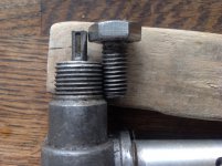
You would indeed be correct and the thread on the speedo drive has a taper on it like a pipe fitting designed to form a seal. It may well be a standard metric pipe thread size but I do not have any data to hand.
If you are checking out thread sizes then a handy way to do it is to have a set of standard size bolts to hand with known thread pitch sizes. M6x1 , M8x1.25 & M10x1.5 etc.
M10 fine as used on the cylinder head nuts drops down a pitch size from 1.5 to 1.25mm so if you put a standard M8 thread next to a fine M10 the threads should mesh perfectly even though the bolt sizes are different.
This method is also quite handy if you want to check those odd bolts in the garage to see if they are metric.
 

Attachments

  • image.jpeg
    image.jpeg
    1.4 MB · Views: 21
That's great. I never thought of that straightforward way to verify the thread. I'm going for a sensor adaptor for the speedo connection which will convert the rotation into digital pulses for very accurate speed and distance readings.
 
If you are going to 'electronic pulses' for your speedo reading, you will probably have to adjust the pulses to obtain the accuracy you are seeking. You may also find that you have to REDUCE the pulses to increase the speedo reading. I have an electronic speedo in my Abarth style instrument cluster, and this anomaly nearly cost me a 'ticket' as my speedo was under-reading as I hadn't realised that this 'quirk' existed.
 
You would indeed be correct and the thread on the speedo drive has a taper on it like a pipe fitting designed to form a seal. It may well be a standard metric pipe thread size but I do not have any data to hand.
If you are checking out thread sizes then a handy way to do it is to have a set of standard size bolts to hand with known thread pitch sizes. M6x1 , M8x1.25 & M10x1.5 etc.
M10 fine as used on the cylinder head nuts drops down a pitch size from 1.5 to 1.25mm so if you put a standard M8 thread next to a fine M10 the threads should mesh perfectly even though the bolt sizes are different.
This method is also quite handy if you want to check those odd bolts in the garage to see if they are metric.

This is a great thing to do, another way and the way I do it is to buy thread files but also use them to measure the pitch on threads.....
 
A thread-file (available in either metric or imperial variants) is always a very useful tool to have in ones tool-box---it can also be used to clean out fine splines.
 
If you are going to 'electronic pulses' for your speedo reading, you will probably have to adjust the pulses to obtain the accuracy you are seeking. You may also find that you have to REDUCE the pulses to increase the speedo reading. I have an electronic speedo in my Abarth style instrument cluster, and this anomaly nearly cost me a 'ticket' as my speedo was under-reading as I hadn't realised that this 'quirk' existed.

I will definitely need to adjust any pulse-driven speedometer to match the car; but the sensor in any pulse-driver is not adjustable. Whether it takes readings from a wheel-hub, driveshaft or speedometer the native electronic pulse simply increases and decreases as the component it reads from speeds up or slows down.

Calibration is achieved by "simple:eek:" computer programming which facilitates the micro-adjustment the speedometer so that it displays the correct speed (and distance covered). If the speedo under-reads you reset it to require fewer pulses per mile. If it over-reads it is set to require more pulses per mile.

If you change tyres, wheels or gear ratios the speedo would need recalibrating. Even the wear and tear on the tyres can affect the accuracy of the reading.

The product I'm looking into is completely unecessary for normal driving and most people here would find it's appearance quite gross.:eek:
But the great advantage is that it can be made to be extremely accurate.
 
Last edited:
Last edited:
This post contains affiliate links which may earn a commission at no additional cost to you.
A thread-file (available in either metric or imperial variants) is always a very useful tool to have in ones tool-box---it can also be used to clean out fine splines.

I also have them in Whitworth and BSF - that shows how long I've been around.... :)

Al.
 
-------------------------------
-----------------------
If you are checking out thread sizes then a handy way to do it is to have a set of standard size bolts to hand with known thread pitch sizes. M6x1 , M8x1.25 & M10x1.5 etc.
M10 fine as used on the cylinder head nuts drops down a pitch size from 1.5 to 1.25mm so if you put a standard M8 thread next to a fine M10 the threads should mesh perfectly even though the bolt sizes are different.
This method is also quite handy if you want to check those odd bolts in the garage to see if they are metric.

^^ This is an excellent way to determine thread pitch.

There's also what are called 'Thread Pitch Gauges' in metric, UNF/UNC, Whitworth/BSF etc available from good tools stores/Engineering suppliers and no doubt online. (Iirc all Cycle threads are 26 tpi so no pitch gauge is needed).

These gauges have fold-out fingers that look like saw teeth along one edge, the no. of threads per inch i.e. thread pitch varies on each and is etched on each blade/finger. To use them, you simply select the gauge that exactly matches the threads and read off the engraved pitch.

As well as different no's of tpi, there are also different angles between the thread flanks depending on whether the threads are Whit/BSF (55*), UNC/UNF (60*). Isometric threads are also 60* flank included angle but obviously the diameter is metric. You need to be careful not to fit nuts of one thread standard onto bolts/studs of another thread type. There are also markings on better quality bolt head and nuts e.g. metric might have 8.8, 10.9, 12.9 depending on strength, whereas Unified will have a no. of lines or small circles to indicate strength. These marking can be used to determine the thread standard being used or to sort out a collection of fasteners.

Older Fiat bolts will usually have Fiat on the bolt heads :), also an 80 or 100? etc. to indicate strength. Many people like to replace standard bolts with one's made from stainless steel - be aware that S/S is not as strong as the stronger grade steel bolts, so don't use them in high load/stress situations.

Don't forget that there are chrome dome headed nuts available in various sizes e.g. 6x1.00mm, 8x1.25mm etc that can look very attractive - I used to replace the nuts holding down the valve cover on my Fiat cars with these chrome domed nuts, sometimes have to shorten the studs they fit onto or else use additional washers, also prevents oil leaking along the threads (often used on motorcycles) - just a thought for those who haven't seen them.

There's lots of info. available on threaded fasteners if anyone is interested.

If you're only working on metric-equipped cars e.g. Fiat, then Toshi 975's method is perfectly adequate. (y)

Al.
 
Last edited:
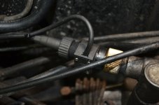
I've fitted the sensor to the speedo-cable output at the gearbox. A squared-section drive-pin is fitted into the slot where the cable usually sits and at its opposite end it goes into a square drive-hole in the sensor. The speedo-cable is then fitted into the opposite end of the sensor.

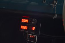
It develops four pulses per revolution of the speedometer cable and this is what is measured in a chunky box of tricks I yet have to fit to the dash.

I've already calibrated the trip-meter and now have an extremely accurate and permanently adjustable indicator of speed and distance travelled. I'm scared to think about it but I guess I'll have to show the interior setup once finalised.

Sheila, Murf and me will be doing our first night rally next month.....but I won't be driving. :eek::eek:
 

Attachments

  • FER_5819.JPG
    FER_5819.JPG
    6.7 MB · Views: 35
I have been looking at fitting a motorbike tacho/speedo to my Beetle.


Due to the major mods on the suspension and steering there is no facility to use the conventional cable drive anymore.


As this is all new to myself I purchased one of these in the first instance..


https://www.ebay.co.uk/itm/Universa...a=0&pg=2047675&_trksid=p2047675.c100005.m1851


However the info that comes with it has no mention or guidance of how to adjust and calibrate the unit so it has just sat on the shelf. Bit of a shame really as it would look good grafted into the single clock dash as a replacement of the original unit and would also give me a tacho without have a spurious unit mounted somewhere.....
 
This post contains affiliate links which may earn a commission at no additional cost to you.
However the info that comes with it has no mention or guidance of how to adjust and calibrate the unit so it has just sat on the shelf.

Given the description says that there is a 10% error in the reading (I suspect that it means +/- 10%), I think they're implying that you're stuck with a set ratio, which would be a bit annoying.

But you have a more elegant arrangement than the one that I've plumped for! But as anyone who knows a bit about rallying will know, the setup I have fitted here is intended for a specific use in timed events. Although it is very accurate now thet I've calibrated it, it takes up half the cockpit and is definitely the proverbial sledghammer to a nut....me being the nut.:eek:
 

Attachments

  • FER_5827.JPG
    FER_5827.JPG
    6.7 MB · Views: 28
Last edited:
Yes but no, it doesn’t give any instructions on any fitment so how far out on a PCD do you fit the magnet to trigger the sensor? The further out the slower the recorded speed etc?!?!
 
Yes but no, it doesn’t give any instructions on any fitment so how far out on a PCD do you fit the magnet to trigger the sensor? The further out the slower the recorded speed etc?!?!

From what I've learned about these sensors there's either a pulse created or not. The distance setting is quite small..a millimetre or two; go too far out and there's no induction created.

If the settings of the speedo are based on the average circumference of a motorbike wheel you could work out roughly the variance on your car.


Ahh that's the magnet to sensor tolerance...…..and yes I agree that potentially the circumference of the wheel has to be taken into the consideration however when you have a sensor and magnet how far from centre do you fit them as from what I understand the closer to the centre the faster it fill think you are going because how else can define speed other than the times the magnet passes the sensor??


Or am I totally missing something?
 
I'm with you now.[emoji3] Maths could work it out. another weak point of mine.... But I would fit the sensor and magnet on a convenient place on the wheel..is there one? Compare indicated speed with satnav on a straight, flat road. If the Speedo reads under, move the pickup closer to wheel hub and vice-versa. ....no......that doesn't work either,,,.......


Ahh that's the magnet to sensor tolerance...…..and yes I agree that potentially the circumference of the wheel has to be taken into the consideration however when you have a sensor and magnet how far from centre do you fit them as from what I understand the closer to the centre the faster it fill think you are going because how else can define speed other than the times the magnet passes the sensor??


Or am I totally missing something?
 
Last edited:
I'm with you now.[emoji3] Maths could work it out. another weak point of mine.... But I would fit the sensor and magnet on a convenient place on the wheel..is there one? Compare indicated speed with satnav on a straight, flat road. If the Speedo reads under, move the pickup closer to wheel hub and vice-versa. ....no......that doesn't work either,,,.......


Yes it would have to be total trial and error, if I don't know what the default setting is I've no chance. By that for instance I mean the centre of the sensors needs to be 200mm from the centre of the wheel for it to work as per its calibrated setting...…


I don't like trial and error on expensive parts.....meaning the car not the speedo...…...The struts and hubs still make my eyes water cost wise....
 
Peter, I don't know how the sensor for your particular unit has to be located,but for the Smiths electronic speedo, the sensor (EMP34-1) can be bracket mounted, and as long as the bolt heads are equidistant (as they are on the 500/126 drive-shaft couplings) it will read off a prop-shaft or drive-flange coupling. The air-gap has to be 2.0mm.
 
Back
Top