-------------------------------
-----------------------
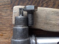
If you are checking out thread sizes then a handy way to do it is to have a set of standard size bolts to hand with known thread pitch sizes. M6x1 , M8x1.25 & M10x1.5 etc.
M10 fine as used on the cylinder head nuts drops down a pitch size from 1.5 to 1.25mm so if you put a standard M8 thread next to a fine M10 the threads should mesh perfectly even though the bolt sizes are different.
This method is also quite handy if you want to check those odd bolts in the garage to see if they are metric.
^^ This is an excellent way to determine thread pitch.
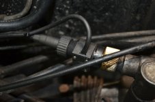
There's also what are called 'Thread Pitch Gauges' in metric, UNF/UNC, Whitworth/BSF etc available from good tools stores/Engineering suppliers and no doubt online. (Iirc all Cycle threads are 26 tpi so no pitch gauge is needed).
These gauges have fold-out fingers that look like saw teeth along one edge, the no. of threads per inch i.e. thread pitch varies on each and is etched on each blade/finger. To use them, you simply select the gauge that exactly matches the threads and read off the engraved pitch.
As well as different no's of tpi, there are also different angles between the thread flanks depending on whether the threads are Whit/BSF (55*), UNC/UNF (60*). Isometric threads are also 60* flank included angle but obviously the diameter is metric. You need to be careful not to fit nuts of one thread standard onto bolts/studs of another thread type. There are also markings on better quality bolt head and nuts e.g. metric might have 8.8, 10.9, 12.9 depending on strength, whereas Unified will have a no. of lines or small circles to indicate strength. These marking can be used to determine the thread standard being used or to sort out a collection of fasteners.
Older Fiat bolts will usually have Fiat on the bolt heads
")
, also an 80 or 100? etc. to indicate strength. Many people like to replace standard bolts with one's made from stainless steel - be aware that S/S is not as strong as the stronger grade steel bolts, so don't use them in high load/stress situations.
Don't forget that there are chrome dome headed nuts available in various sizes e.g. 6x1.00mm, 8x1.25mm etc that can look very attractive - I used to replace the nuts holding down the valve cover on my Fiat cars with these chrome domed nuts, sometimes have to shorten the studs they fit onto or else use additional washers, also prevents oil leaking along the threads (often used on motorcycles) - just a thought for those who haven't seen them.
There's lots of info. available on threaded fasteners if anyone is interested.
If you're only working on metric-equipped cars e.g. Fiat, then Toshi 975's method is perfectly adequate.
Al.