1677188756264.png

600 (Classic) 1960 600 EV conversion

Introduction

Hello all... I am new to this forum and I am in the midst of converting my 1960 600 to electric. I have converted one other classic car to electric 3 years ago (1964 Corvair) and it has been wonderful. The corvair is a convertible and we drive it daily all summer (in the pacific NW). I want a classic ev conversion that will also allow us to drive year round. Thats where the 600 comes in. We are all small car fans in this fam, and this little guy is just too damn cute. I have been working on the car for about 6 months at this point, and now that I have worked out most of the big-ticket items, i thought it was time to share it with y'all.

First off, i know there is alot of controversy about converting old cars to electric. Everyone will have their own opinion on if its the right thing to do or not. I can tell you, for me, its totally the right thing to do, for many reasons. With that... lets get to it.

My goals:
- 120 miles of range
- 75mph top speed
- Safer than it was
- Looks stock
- Can still haul 4 people
- Use it all year

The major parts i plan to use:
- Hyper9 144V AC motor and controller (@ 120hp/180ft-lbs this motor is WAY too big for this car. its a long story, but its what i ended up with)
- (6) Tesla model s battery modules
- Orion2 BMS
- 2.5kW charger
- Early beetle transmission (why? well, they have loads of aftermarket support and they have been used in countless EV conversion with the motor i plan to use. out little transmissions are just too unique and unknown, in comparison).

The major things i needed to figure out right away:
- where can i stash all these batteries?
- will the motor fit in the back
- how will i manage the HVAC? (since i want this to be usable year round)
- how will i upgrade the brakes?

This first couple of posts will get after the batteries and the motor fitment.

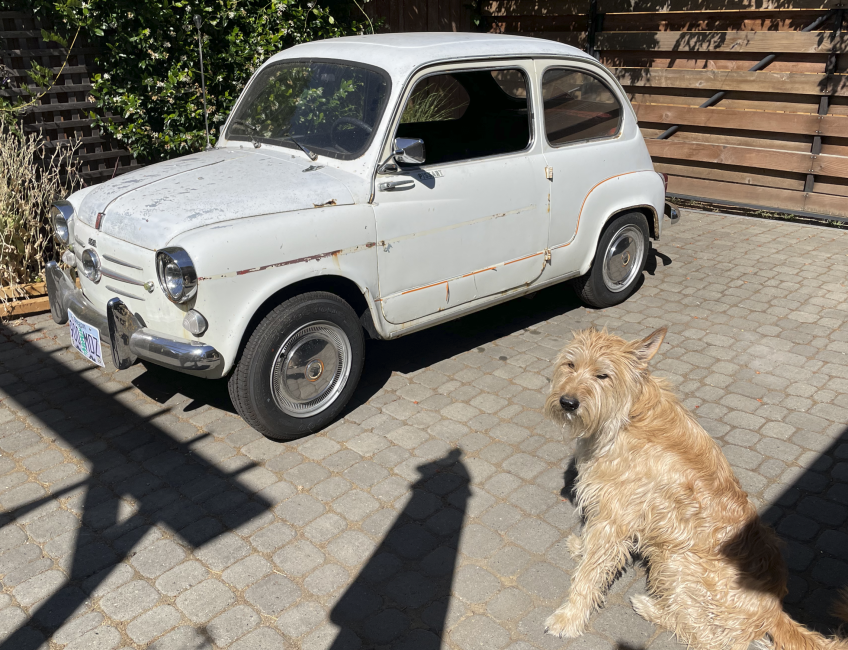
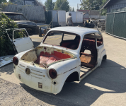
here is the car as bought:
1677188756264.png


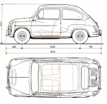
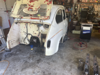
I bought the car in august 2022. Clearly my dog Marty is super excited about all the time i will be spending working on it, rather than going for walks. The car had spent alot of its life at the coast, so the rust is not ideal. This is my first body work project, so I dont expect it to be a show car. When i was planning this conversion, i carefully measured up where and how i could fit the (6) battery modules in the car. Most of the old Fiat conversion (mostly 500s in the UK it seems) use (3) tesla modules and place them under the bonnet and boot. The floors in this car need replacing, so i worked on a plan to place the batteries under the seats, just like modern EVs. It will keep the center of gravity low and give me space for other stuff up front and have storage in the back. Here is some cad exploration: You can see the battery module outline in orange.
1677188973641.png


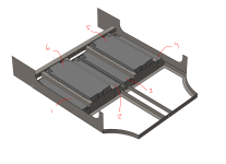
So, according to my rough CAD, i could fit 4 modules across the bottom of the car, and then one additional module under each front seat, between the seat rails. It will lower the floor of the car about 1.25in and raise the seat about 1in. The new seat rails will be on either side of modules 5 and 6. Like this:
1677189217454.png


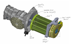
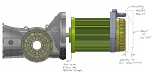
This will give me a voltage range of about 108-151V. The motor and motor controller i chose can support 90-180V, so its just right. Speaking of the motor, i made sure it will fit between the transmission and rear bumper panel. I also found a CAD model of a beetle transmission so i can work on new mounts and adapter plates. Here is how it is coming together:
1677189800457.png

Note the clearance to the back of the car and how i plan to use the existing motor mount to hang the back of the assembly from. I will also be working on getting the standard transmission mounts adapted to the car, but i am less concerned with that, at this point:
1677189865602.png


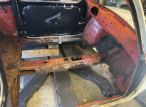
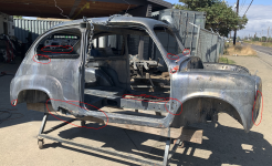
So, now that it doesnt seem totally CRAZY to fit all of this stuff in the car, I got to work taking the car apart, preparing it for a metal dip. Here are some progress pics of the tear down (note the car was originally red):
1677190398627.png


here you can see how rotted the floors were:
1677190464594.png


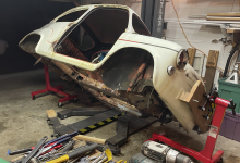
I also built a makeshift rotisserie out of harbor freight engine stands. I cant flip the car over completely, but i can rotate it 90deg either direction.
1677190555284.png


After completely stripping everything off of the car, it was time to haul it to the metal dip shop (in Eugene OR, totally awesome place):
1677190641567.png


When the car came back from the dip shop, i was heartbroken. i had a big decision to make... it was bad. Really bad. Should i scrap this car? I considered it. I would have to replace nearly everything. Even the doors were completely unsalvageable.
1677190955199.png


I had to source replacement doors. The only early (suicide) door i found on Ebay was 1000$. If i had to spent 2k$ on doors, this project was sunk. I decided that if i couldnt find reasonably priced doors, i was going to scrap it. Then i discovered Chris Obert down in Santa Cruz CA. He had 16 doors for me to choose from and sells them for 150$ ea. He was kind enough to take a video of each door, reviewing their health and let me choose. it was awesome. the project was back on!
I have been on holiday break, and I spent a fair bit of it in the garage. I have said it before, and I will say it again... this part is sooo fun. I focused on getting that rack and pinion conversion completed, got a solid start on the high voltage wiring, and worked on interior bits and bobs. First up, the steering. I had three goals with the steering. 1. Use the stock steering wheel. 2. Install a quick release steering hub. 3. Convert the car to rack and pinion steering with a kit and a nudge from Ricambio.

To use the stock steering wheel, I had to bravely cut off the hub to make room for the quick release mechanism. I made sure I could source another steering wheel in the event I bunged it up, but so far so good. I also ordered some parts from sendcutsend to interface the old wheel with the new hub. I think most shops assume that an aftermarket wheel gets used when installing a quick release hub. The bolt patterns are sorta standardized, so... order a hub, a new wheel with the same bolt pattern and you're off to the races. I decided to make it hard on myself by grafting the new hub onto the old wheel, hence the new laser cut parts. The aluminum part bolts to the hub. The steel part gets welded to the steering wheel, and then gets bolted to the hub through the new aluminum part. Here are some pics to explain (the wheel still needs restoration)... here is the freshly cut-up steering wheel:
1703814035312.png


This shows the new steel part welded into the old wheel:
1703814128064.png

And here is the old wheel bolted to the new quick-release hub, installed on the steering column:
1703814550889.png

and with it removed, which will be for security:
1703814616242.png


The rack and pinion work was a challenge. I had to design a part that took advantage of the stock steering box and idler mounting points while allowing the new rack to be in the right location. It also required that the steering shaft get cut short and redirected with some u-joints, between the accelerator and brake pedal, through the floor and onto the new rack and pinion input shaft. Here is the interface part:
1703814810452.png


The new steering shaft will come out of this professionally cut hole:
1703814944124.png


Here is with the rack installed:
1703814878071.png


And inside, the new steering linkage turned out like this... its a combination of 3/4in DD u-joints and a 1in DD for the stock steering shaft:
1703815058428.png


Note that I had to add that pillow block bearing to stabilize the stock steering shaft, towards the top. I also added a bearing at the floor to stabilize the 3/4in shaft that passes through the hole. You can barely see it behind the accelerator pedal, which is now installed (and i painted everything black to help hide it):
1703815184978.png


Now that steering is in good shape, I got to work installed the motor and transaxle assembly for the last time (hopefully!). This enabled me to start the high voltage wiring... specifically from the motor controller under the back seat to the motor. I also started on the my contactor bank and fuses. Here is the motor assembly going in:
1703815330568.png

Funny side note: I filled the transaxle with gear oil before installing it and wouldnt you know it? there was a nice, big leak out of the backup switch. My precious, expensive, and super late transaxle leaks. And not a little. So, I spent half a day hunting for an M10 pipe thread plug. Not easy to find in the USA. With that fixed, I got to work on the wiring. I also got to place 4 of the 6 battery modules (exciting!!!). Here is my contactor bank. From left to right: the 12V dc to dc converter to charge my 12v battery, then the cabin heater, and then the 48v converter to run my A/C and HVAC blower. Each one of those white boxes are fuse holders, so each contactor has its own fused output.
1703815619914.png

Here is the wiring from the motor controller to the motor. I am using an AC motor, which is why there are three cables...
1703815745895.png

the cables pass through the old heater tunnel and out the back to the motor assembly:
1703815818643.png


Soon I will start on the battery wiring, but before that happens, I need to work on the trim and the new floor pieces. I made up two big "tubs", for lack of a better word, out of 3/16in ABS. I scored it with a circular saw, then used a heat gun to create the bends. Here is a pic of my scoring setup, with my level as the fence:
1703816211209.png


Then it gets heated up with the heat gun and bends are added. These parts cover up the batteries and live under the new seat rails:
1703816340071.png


There is one for each side. In between them, I plan to run the high voltage cables from the battery modules to the motor controller. In that channel will live two 500A fuses and a cut-off switch. The switch needs to be accessed from the outside. Here is the new console cover, with the cut-off switch in its final location:
1703816469376.png


In other news, I installed the rear window and headliner. The headliner was a PITA, and turned out only OK. The exciting part is that the rear window fits, and fits really well! After all that sheet metal work I did a year ago, I was really nervous it wasn't going to fit well. Phew!
1703816577471.png

and from the inside:
1703816605044.png

Exciting times!
 
Hats off to you more patience than me.
It's looking fantastic, I'm still cautious about the safety side of electric vehicles myself.
Think a sunroof might have been a good addition.
If removable steering wheel is for security, when out will you just clip it on your keyring?
 
Hats off to you more patience than me.
It's looking fantastic, I'm still cautious about the safety side of electric vehicles myself.
Think a sunroof might have been a good addition.
If removable steering wheel is for security, when out will you just clip it on your keyring?
I had a necklace in mind, Flavor Flav style. But a keyring is also good.

Or I will just put it in the “trunk” since it will now be lockable.
 
Last edited:
Hello everyone... the cold weather has slowed progress a bit. I did get some battery wiring done and the console plate engraving and wiring done. Now the havc switches have connectors, the direction knob has a connector, and all are backlit. I also completed the call tap and thermistor wiring for the battery pack. First up, the console. Engraving went fine and now looks like this:
1705454667240.png


One thing thats weird about an EV is knowing when its "on". Without an engine running, I could rely on the key position to tell me, but without feedback (like a light) its impossible to know if the car is actually on. What if a kill switch is tripped, for example? They key would be on, but the car wont respond, and that can cause a panic. So, I built in light indication under the direction knob. It will light up when the car is on, and will also be back lighting for the R, N, D, L under the knob. I chose HVAC knobs with backlighting to know when they are on. The fan switch is the master for the heater and A/C meaning, if the heater is on, the fan must also be on. If i turn off the fan, the heater will also turn off. This is to prevent overheating or running the a/c for no reason, accidentally. Here is how the "car is on" backlighting turned out:

1705455087801.png

and during the "day" with the hvac switches on:
1705455132278.png


Next up is getting the battery pack wiring complete and cooling lines run. I have the cell tap harness built, which includes the thermistors. Each battery module has a thermistor and 6 cell taps. Like i mentioned before, the order of the cell taps is vital for the battery manager, so before I can declare it ready, I have to test the harness with a validator tool. Those are available for rent from Ewert Energy systems, who makes the battery manager. I have contacted them to rent one. Fingers crossed its all ok when i test it. The battery modules must be modified to enable external cell taps. To do that, the PCB in the battery module must be replaced with something. I chose a molex mini-fit connector. If anyone ends up with an early generation Tesla model S modules, the cell taps are labeled in this pic of the PCB that was removed in favor of the connector:
1705456619590.png


All those wires get snippet carefully and inserted into the replacement connector like this:

1705456257730.png


and, sadly, while building a cell tap wiring harness may sound exciting, it doesnt come through well in pics. Nonetheless, I am including a pic anyway... public service announcement, if bundles of loose, partially labeled wires gives you nightmares, you may want to skip this one:

1705456383749.png


The batter manager has a nice harness with labeled and color-coded wires to make this as easy as possible, but it still requires 50 or so connector crimps (and i solder them for good measure). The schematic for this portion has been updated and looks like this:
1705456806799.png


One last thing for today... given all the frigid temps in the USA, I have seen lots of headlines about EVs and their owners suffering a bit. This is all true... like humans, batteries slow down when they are super cold. They are also slow to charge until they warm up a bit. I am addressing this by adding heater pads under each battery. These are heater pads designed for keeping water tanks in RVs from freezing. The units I chose operate on 120v ac and have built in thermistors so they turn on and off automatically based on temp. This means, for my little Fiat, when it gets super cold, I will plug it into my charger at home and use the wall AC. I wired it to pass AC through to the heater pads (and buck it to 120v even if the charger is plugged into 240v) to keep the modules warm. I anticipate this will also take the edge off in the cabin, but we will see. This also means that unless the car is plugged into a charger, the batteries will be at ambient temp. So, if I am out and about and it gets super cold, I will have batteries that are sluggish. This is a specific use case I am willing to accept and if you decide to do an EV conversion, you can solve for cold temps some other way if you want (like heaters that run off the traction batteries themselves). I did this for simplicity and easy of wiring. The pads I installed fit nicely under the battery modules:
1705457498130.png


Next up is to test the cell taps, pending the validator tool, and get the cooling lines routed under the back seat. This will allow me to put the batteries in their final location and start some testing (motor spinning, charging the 12v battery and charging the traction pack). It will be much nicer to work in the garage when this cold spell is over.
 
Looks like it's coming along nicely, any reason why youve put those controls next to gear lever and not on the dash?
I admire your enthusiasm and level of detail, I'm tired out just reading it.
Good luck.
 
Looks like it's coming along nicely, any reason why youve put those controls next to gear lever and not on the dash?
I admire your enthusiasm and level of detail, I'm tired out just reading it.
Good luck.
Good question @stocky ... I want the dash to look stock. I really love the simplicity and want to honor the original design, so to keep the dash and gauge pod looking as stock as possible, the new functionality was added to the area I was already butchering for the conversion. This is the solution that fit best with those goals in mind.
 
Howdy, folks. There has been some progress on things here and there. Mostly four things... 1. I attempted the "final" installation of the traction battery pack. 2. I spun my new motor for the first time! 3. I continued with a bunch more 12v wiring. 4. Finally installed the front brake calipers and filled the system with fluid.

First, the battery pack. This needs to be working for the motor to be spun, so I focused on getting the modules wired up, into place and ready for testing. They each weigh about 55lbs, so its tough on ones back. The good news, they all slid into place, and wired up. The bad news, while wiring, I had to rearrange the order of the modules. This means my cell taps are no longer correct. So, it all has to come out again. I am telling myself that this journey is really about the process. Enjoy the process, Summer. Enjoy the process... anyway... The large wire is 2/0 gauge to handle the 500 or so amps my motor will get under full throttle. This means, for short lengths, it is VERY stiff. Care must be taken to make sure that the cable doesn't impart large forces on the terminals when changing length from heat. Here are some progress pics:
1706890699706.png

and with the lower covers and console cover: i still need to add protection, fasten and covers to the seat modules.
1706890803615.png


Next up was to initiate the motor. There is some fancy software that comes with the motor to set it up. It does a calibration routine called "commission spin sensor" to tune the control loop for this exact motor. Then I can program the behavior for the accelerator pedal, brake pedal, etc. Its also my first test of the "direction knob" on the console. There is not much to see here except that i spent time with my laptop plugged into my 1960 Fiat... which always makes me smile. The documentation for the motor is ok. As long as things behave as expected, its good enough. If things go wrong, i find the documentation to be pretty poor. Folks have started a thread on a diy ev conversion forum specific to this motor to help each other troubleshoot. I dont like the vibe of that forum, so I dont post on it. This forum is perfect to document a project like this. Thank you all!
1706891136344.png

Now my motor spins forward and backward. Big step! If I had axles, I could technically take it for a drive, windshield free. Crazy times.

I did some minor 12V wiring as well. I installed cabin lights, along with the door plunger switches to turn them on and off. Snaking wires through the old bones of this car was a fun challenge. Swear words were plentiful. I installed the gauge pod and wired up the dash toggle switches. I found these groovy toggle switches that have built in lights. I also got that lower dash pad installed.
1706891339328.png

here is my solution for cabin lights, though I am not sure how much I like them. They really highlight my mediocre headliner:
1706891445327.png


The brakes are next. After a frustration few months, I have finally installed the front calipers. In the end, the only parts I used from the oldtimers shop conversion kit are the adapter brackets, caliper brackets and rotors. Everything else i had to buy again. I also learned that the 124 caliper brackets and the X1/9 caliper brackets are slightly different and require different bias springs, though they both use the same calipers. I finally put fluid in the system and am now working through leaks and getting it properly bled.
1706891634905.png


In other news, I saw that @dietz imported a fantastic 600 to the USA from Argentina and it is sporting Cromodora CD-16 wheels. Serendipitously, I had ordered those same wheels for my car (Midwest Bayless had a used set with tires). It was nice to see how great they look. I plan to finish mine in bronze. They were one of the few wheels I like that have a reasonable offset for my car, and its still quite aggressive. I will put them on for the days I am feeling sporty or if I ever autocross this car. The 185 width looks massive on this little car. A 185 width tire that makes this car look stuffed makes me laugh. I still plan to have the steelies, with juicy white walls, for my cruiser days.
1706892099678.png


Next up... I will be taking my traction battery apart (this is a TRUE test of how serviceable it is) and fixing the cell taps. Then its battery manager and charger wiring. and then axles! Things are cookin.
 
I am now waiting on axles before I can test drive. I found a local axle shop that will be making them for me. They typically do axles for big 4x4s so they dont stock the tiny diameter materials... so they have to order it. I guess there is a surge in demand in the spring, when all the car folks start getting their rides ready for the summer. That is also slowing things down. I estimate that 4 weeks from now (middle of march) I can start testing.

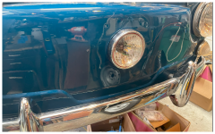
In the meantime, I am getting lots of other stuff done. I worked on the BMS, charger, and finishing out the interior. The BMS is now fully functional and monitoring all the battery cells for voltage and temps. With a working BMS, I can now work on the charging circuit. This meant I could finally install the charge port under the 3rd headlight. I use a magnet to hold the light up when I am charging. The port is rather deep and dark so I had planned to get a convenience light installed... but wasnt sure how I was going to activate it. I happen to have a few magnetic reed switches, and I was able to position one so that the same magnet that holds it up when its open also turns off the light when closed. I love dual purpose stuff! Here are some pics:
1708369098377-png.438637

And with it open, light on:
1708372199889.png

I am very pleased about how out it turned out! Its tough to tell in the photo, but there are two circuit boards inside the 3rd headlight that will glow based on charge status (red, yellow, green).
1708372338354.png

Inside, I finished up the battery cover and got some seats installed.
1708372506243.png

the rear seat now has locking latches accessible only in the boot. The new boot will be lockable, so now we will have secure storage in the car. I found these nice cam lock latch thingys:
1708372646876.png


and finally, I have been dreading installing the windows in the door, along with the regulator pully system, trim and tracks/fuzzies. In the end, it all worked, but it took alot of time! I ordered generic window channel/tracks from https://www.rubbertherightway.com/i...el-flexible-8-strip-17-32-tall-9-16-wide.html . Too bad the company name is so cringe worthy... they have great stuff. I ordered new chrome window trim from ricambio, and it came with fuzzies. They are a bit wavy, but turned out nice enough:
1708373081524.png

and the pulley system installed without much fuss. Does anyone know how much tension there should be in the cables? I made it high enough to ensure the cable wouldnt jump out of the track on the winder pulley... which ended up pretty tight.
1708373173760.png

the windows move up and down so smoothly now! and with no rattles when closing the door. fresh.

and one last thing... i want the car to make noise when backing up. Rather than the typical (and annoying) backup signal i hear on delivery trucks, I opted to make a bell. I used a bike bell and a 12V gearmotor to make a music box of sorts. I can change the grey plate to change the bell ringing pattern. This is not required, but really fun. I bet it will last 6 months before breaking somehow.
1708373411706.png

ill cover that and fasten it to the bottom of the car. Ill wire it to the backup lights.
 

Attachments

  • 1708369098377.png
    1708369098377.png
    5.6 MB · Views: 212
You'll be finding all sorts of reasons to drive in reverse! I predict your backup bell lasts longer than the Fiat window pulley system! Lovely work; Is that your own 3D printed enclosure?
 
You'll be finding all sorts of reasons to drive in reverse! I predict your backup bell lasts longer than the Fiat window pulley system! Lovely work; Is that your own 3D printed enclosure?
ha! you may be right. that pulley system does seem fragile... in fact the passenger side makes a nice crackling noise that i hope will just go away as it gets used. I do have access to 3D printers, so yep!
 
Slow but steady progress for me lately. While i wait, I am doing a bunch of odds and ends... putting in the last of the windows, wipers, door moldings, and music system.

It feels good to put all the windows back in the car. The windshield took two people, but once we got it started, it went smoothly. The rope method really works well. If you dont know about this method, here is a video: . I wiped some armour-all on the window wells, and rubber bits. It helps keep things from sticking and tearing but can also make it slip right out of its location. The windshield took two because it needed some serious pushing to get it into place. The rest of the windows I could do myself. After getting the windshield in, I could finish up the wipers and such. After a few test wipes with my new wiper blades, one promptly exploded. They are sending me a new one, but it suspect this will happen again.
1709679803945.png


Before I put the side windows in, I worked on placing little speakers in the back corners. It sounds only ok.
1709679873188.png

they are component speakers and I stashed the tweeters under the dash, firing up through the defroster vents. I also have a speaker under the rear seat that is my "sub" though it mostly just vibrates the bottom of the back seat.
1709680028434.png


Next up was the door molding. I think the molding for the doors is supposed to attached to the car and contact the door when it closes. The gap around the door itself is perfect for some generic door molding of this profile:
1709680111263.png

and it comes with tape, which is so much cleaner and easier than molding glue. It looks like this when its in:

1709680171179.png

it doesnt block the drain holes in the bottom of the door either and looks really good. To make sure the rubber actually touched the door frame all the way around, I used paper strips as 'feeler' gauges. When the rubber touched the door frame, there was obvious drag on the paper when I pulled on it:
1709680279908.png
in the locations where the rubber was not touching, or not touching enough, i added a layer of molding tape behind to rubber to space it off a bit, which helped seal it up. I only had to add 30cm or so near the bottom corner on each door.

Not a very exciting update, but an update nonetheless. I will get after the steering wheel and the console next, i think. I am reluctant to do too much before test driving in the event I have to tear it all open.
 
Hey all... Ive got some exciting news... the Fiat drove around under its own power this weekend! Its kind of a miracle, if you ask me. It worked right out of the garage.... mostly. What does "mostly" me, you might ask? Well, it was not a perfect maiden voyage. Let me just say the car accelerates, and turns like a pro. Stopping? Not so much.

First off, the axles. They arrived on time and on budget. They also went into the car without much fuss. I think they are rather beautiful:
1710876670684.png

One end is VW and the other is Fiat. They are not equal lengths. The passenger side is exactly 25mm longer. I did not feel anything with our short test drives, but I have heard it can create some torque vectoring. We will see. They look even better in the car:
1710876770845.png

I went through my "pre-drive" checklist a few times... torqued wheel bolts, greased all points, checked suspension bolts, battery status, etc... and it was time to back it out of the garage. I am super happy to report it was successful.
1710876909453.png

It looks so great on the ground. We were able to drive it up and down the street a few times. A couple things of note:
- The wheel/tire combo is a very tight fit. Very tight. I eyeballed the toe and camber on the front and had to change it slightly to keep the fronts from rubbing on bigger bumps.
- The ride height is nearly perfect. The rear passenger side is perfect, but the rear drivers side is a bit low. Don't ask me why they aren't the same, I have no idea. I hope they will settle into being the same, otherwise I will be adding a shim. I suspect I will be shimming the back when I corner balance the car anyhow.
- the transmission is surprisingly easy to shift without the clutch. I simply wait for the motor is coast down and with alittle pressure, it slips into gear without much effort at all. I wont be winning any drag races with my speedy shifting, but I was tickled that shifting on the go is so easy. I reckon it will take its toll on the synrcos over time.
- The suspension is firm but feels appropriate for the car.
- The car is a ROCKET in first gear. Shockingly fast. It has a solid pull in second, which is what we will be in most of the time. The battery pack was at 50% so it can get even peppier. I am very pleased. The car will even accelerate in 4th, even though its not happy about it.
- The brakes completely failed. Thankfully, my sweet parking brake hack (squeezing the clutch) worked and we were able to stop the car safely (albeit with a tremendous amount of clutch smoke... it smells delightful). How did the brakes fail, you might ask? A broken fitting. I am very glad this happened at 20mph and not on the freeway:
1710877323832.png

These master cylinders are readily stocked and I already have one on order. At only 65$, its cheaper than the time and purchasing the tools to try and extract that npt fitting. Fortunately, it is also very servicable and was out of the car in 20mins:
1710877634751.png

Sooo... I have to say it was more successful than not. I am very pleased.

In other news, I washed the car for the first time. I wanted to see how well the windows and doors seal. I did not anticipate how much water would get through the doors without the door cards. I am SO glad i did this. Now i will be lining the inside of the door cars with plastic. I put down towels to see how much water would come in and they were SOAKED. All the windows sealed, and no water got under the bonnet. Good news.

I also got some solid charging time in. I think its wise to charge a conversion outside the first few times to make sure everything is ok. I only got to 80% before I had to leave it unattended, so I unplugged it, but it worked fine. I will be working on some lockout settings, max cell voltage stuff, etc...
1710877952308.png

Its so damn cute.

I also got a healthy head start on the battery cooling network. I have been dreading this, mostly because it wasnt perfectly clear to me how it was going to come together. But, I had some inspiration and everything fell into place. Its not as neat as the Corvair, but its functional. But before I did all the plumbing, I wanted to make sure the battery connections were not leaking at all. How to test? I used an old pressure gauge for the Corvair carb balancing and a bike pump to charge each battery circuit to about 5psi and watched for leaking. All 6 passed:
1710878137305.png

And now with all the manifolds in place under the back seat sheetmetal:
1710878197838.png

1710878227892.png

That big heatsink is the motor controller. It was tricky to work around and I could have been better about planning for it.

Lastly, my buddy drove his 308 over for my Fiat's first Italian meetup.... The cherry blossoms are out.... It was an awesome weekend.
1710878387695.png
 
Hey all... Ive got some exciting news... the Fiat drove around under its own power this weekend! Its kind of a miracle, if you ask me. It worked right out of the garage.... mostly. What does "mostly" me, you might ask? Well, it was not a perfect maiden voyage. Let me just say the car accelerates, and turns like a pro. Stopping? Not so much.

First off, the axles. They arrived on time and on budget. They also went into the car without much fuss. I think they are rather beautiful:
View attachment 440332
One end is VW and the other is Fiat. They are not equal lengths. The passenger side is exactly 25mm longer. I did not feel anything with our short test drives, but I have heard it can create some torque vectoring. We will see. They look even better in the car:
View attachment 440333
I went through my "pre-drive" checklist a few times... torqued wheel bolts, greased all points, checked suspension bolts, battery status, etc... and it was time to back it out of the garage. I am super happy to report it was successful.
View attachment 440334
It looks so great on the ground. We were able to drive it up and down the street a few times. A couple things of note:
- The wheel/tire combo is a very tight fit. Very tight. I eyeballed the toe and camber on the front and had to change it slightly to keep the fronts from rubbing on bigger bumps.
- The ride height is nearly perfect. The rear passenger side is perfect, but the rear drivers side is a bit low. Don't ask me why they aren't the same, I have no idea. I hope they will settle into being the same, otherwise I will be adding a shim. I suspect I will be shimming the back when I corner balance the car anyhow.
- the transmission is surprisingly easy to shift without the clutch. I simply wait for the motor is coast down and with alittle pressure, it slips into gear without much effort at all. I wont be winning any drag races with my speedy shifting, but I was tickled that shifting on the go is so easy. I reckon it will take its toll on the synrcos over time.
- The suspension is firm but feels appropriate for the car.
- The car is a ROCKET in first gear. Shockingly fast. It has a solid pull in second, which is what we will be in most of the time. The battery pack was at 50% so it can get even peppier. I am very pleased. The car will even accelerate in 4th, even though its not happy about it.
- The brakes completely failed. Thankfully, my sweet parking brake hack (squeezing the clutch) worked and we were able to stop the car safely (albeit with a tremendous amount of clutch smoke... it smells delightful). How did the brakes fail, you might ask? A broken fitting. I am very glad this happened at 20mph and not on the freeway:
View attachment 440335
These master cylinders are readily stocked and I already have one on order. At only 65$, its cheaper than the time and purchasing the tools to try and extract that npt fitting. Fortunately, it is also very servicable and was out of the car in 20mins:
View attachment 440336
Sooo... I have to say it was more successful than not. I am very pleased.

In other news, I washed the car for the first time. I wanted to see how well the windows and doors seal. I did not anticipate how much water would get through the doors without the door cards. I am SO glad i did this. Now i will be lining the inside of the door cars with plastic. I put down towels to see how much water would come in and they were SOAKED. All the windows sealed, and no water got under the bonnet. Good news.

I also got some solid charging time in. I think its wise to charge a conversion outside the first few times to make sure everything is ok. I only got to 80% before I had to leave it unattended, so I unplugged it, but it worked fine. I will be working on some lockout settings, max cell voltage stuff, etc...
View attachment 440337
Its so damn cute.

I also got a healthy head start on the battery cooling network. I have been dreading this, mostly because it wasnt perfectly clear to me how it was going to come together. But, I had some inspiration and everything fell into place. Its not as neat as the Corvair, but its functional. But before I did all the plumbing, I wanted to make sure the battery connections were not leaking at all. How to test? I used an old pressure gauge for the Corvair carb balancing and a bike pump to charge each battery circuit to about 5psi and watched for leaking. All 6 passed:
View attachment 440338
And now with all the manifolds in place under the back seat sheetmetal:
View attachment 440339
View attachment 440340
That big heatsink is the motor controller. It was tricky to work around and I could have been better about planning for it.

Lastly, my buddy drove his 308 over for my Fiat's first Italian meetup.... The cherry blossoms are out.... It was an awesome weekend.
View attachment 440341
I wish I would have saw this Italian meetup going on outside. I would have backed my Moto Guzzi in right between them for a photoshoot.
 
I've been following this along since the start, I am a fan of EVs and obviously a fan of Fiat's too so this is a great little (or maybe not so little) project.
Do you think you'll just stick with one gear and use that for all of the driving needs or will you actually change gear? Does it still have a clutch pedal?
Thanks, @Didge3. It's been a fantastic, but huge, project for me. I have been way over my skis on this one. And I still have loads to do.

I have no clutch pedal or flywheel. The motor is directly coupled to the transaxle. While I do still have the clutch disc in there, I have repurposed it for the parking brake, and mostly just wanted to take advantage of the spline to mate with the transaxle input shaft.

As for the gearing, I had planned to just use 2nd for around town (top speed of about 60mph, best between 20-45mph), and 3rd for highway (top speed of about 85mph, best between 35-70mph). I assumed, while stopped, I would put it in "low" for driving most of the time, and then, while stopped, put it in "high" when going on the freeway, sacrificing acceleration.

But now that it seems pretty easy to shift (up-shift specifically... I suspect it won't be as easy to down shift but I haven't tried rev matching yet), I think I can always be in 2nd (low) and when I will be at higher speeds for any length of time, i will just slide it into 3rd (high).

I have to say, this news is extra fun for me because I assumed I would never really use 1st. The top speed in 1st is about 30mph. But if I can just shift to 2nd now, I will likely use 1st often to really put a smile on my face. It is a ROCKET in first... to 25mph. :p I gunned it with my kid in the passenger seat and he kinda freaked out. Priceless. Cool dad points for sure.
 
The car now has about 20 miles on it. I am working out some kinks as i get after some of the finishing touches. I have been working on refinishing the steering wheel, adding some trim, corner balancing the car and dialing in the ride height. First up... corner balancing and ride height.

The rear right and rear left of the car sit at different heights. This is the first problem for me to solve. I had hoped they would settle to be about the same after some driving, but no such luck. Over the weekend, i swapped the springs (left to the right), to see if the height difference was because of the springs, but nope. There is something about the way the car came together that makes the drivers side rear sit about 15mm lower (kind of alot). And this is without me in the car. What to do? Well, I cadded up some spring spacers and am having them cut out of ABS. I got 5 spacer "donuts" that will sit above and below the spring, in the spring perch, each about 6mm thick. I plan to add 3 to the drivers rear. This should level out the car in the back. This comes at a cost however... corner balance. Now, the corner balance is all messed up. I did my best to bring the balance back in with the front adjustable springs, and i got pretty close, without impacting the ride height in the front too much. Here is a quick note for the folks that dont know what corner balancing is... its nearly impossible to get all the wheels to have the same load. In the case of my 600, the rears are holding up more. More so, its hard to make the left and right, at each end, have the same force. Add a driver, and it gets even worse, since now the driver's side springs are hold up more. So... what to do? Well, some clever folks realized its not that important that each tire hold up the same amount as long as the RATIOS between the front and the back, on the same side of the car, are the same. This ensures that when the car is cornering, regardless of direction, the grip behavior is consistent. The total grip may be different between left and right, but the tendancy to oversteer/understeer will be the same. This is the safest and most predictable. For an extreme example, lets pretend that on the right side, the front and back tires are holding up exactly the same amount. But on the left side, the rear tire is holding up 80% of the car. If I am turning right, the car may be well balanced and both the front and rear tires lose grip at the same time. But if i am turning left, the rear tire is doing WAY more work holding up 80% of the car on that side, and will lose grip first, resulting in oversteer. Turn right, and its fine... Turn left, and it oversteers? not a good combo. This is where corner balancing comes in. The best analogy i have heard is a 4-legged stool. If one of the legs is shorter (doing less work than the others) the stool will wobble. A couple things of note: 1. you cant do this if you have any anti-roll (sway) bars hooked up, so those need to be disconnected first. 2. this really only applies for cars intended for very spirited driving OR have a high spring rate. I have a very high spring rate in my setup, so small changes in compression result it large changes in load. Most daily driven cars dont care about corner balancing, but I love this stuff, so here goes! The target is to get the opposite corners to hold up 50% of the car. Like this:
1712085454160.png

Thats the goal. Here is my setup (i borrowed scales from a buddy of mind, you can see the oil under the scales to help the suspension settle):
1712085748784.png

And my first reading is this:
1712085799049.png

There is lots of good info in that pic.
  1. I now have a total weight, post conversion. I predicted I would add at least 245lbs. I added just under 300lbs total. This makes sense, since i did not account of a bunch of things like wires, charger and other electronics. The car started at 1340lbs, according to the cyberwebs. I had a secret hope the car would be under 1700lbs when all done, and it happened! woot. This helps explain why its so dang fast.
  2. I now know the front/rear ratio. I predicted it would be 46% front and 54% rear. Instead, I got 43% front and 57% rear. not bad. The car started at 38% front and 62% rear according to the interwebs.
  3. The corner balance is pretty lousy. Below is a calculator I have to keep track of the impact of any changes.
    1. First measurement with no adjustments (after lowering the car onto the scales, you have to move the car around, compress the springs, etc to get rid of any "stiction" in the suspension in order to get a reasonable measurement. I also oiled the scales. this is a pain.)
    2. Second is a measurement where I corrected the ride heights (with spacers or twisting the adjustable springs in the front of my car) so they are the same left and right.
    3. Third is the same as the second, but with me in the car.
1712087065387.png

So, its probably good enough, but I will likely remove a turn or two from the LF so the balance is 50/50 while I am in the car. Phew! My donut spacers are supposed to arrive over the weekend, so I will take the rear end apart again and get them installed, then tweek the front springs to dial everything in. Then its off to get an alignment!
 
Back
Top