The wiring on the stereo
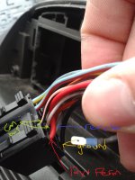
Here is what the canbus stereo is like


As you can see from the front, where the 12v Switched feed should be - the pin is missing, there is nothing there, as this is now done via the can bus
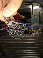
and here is what your stereo connection may look like
These do vary

Did you notice that suddenly colours have now changed as well? And that there is now suddenly an extra wire
This is where it gets a little confusing, but bear with me
- Black is still black for ground - Ensure these pins meet
- Remote lead (12v signal for subs/amps) Goes from Grey to blue, this guide aint bothered about this right now
- The 2 canbus wires, dont have anything to connect to, thats important
Note: DO NOT USE THESE WIRES TO PROVIDE 12V SIGNAL TO AFTERMARKET UNITS. THESE ARE NOT 12V POWER LINES, BUT MORE LIKE 12V DATA LINES. THESE SEND PACKETS OF INFO AROUND THE CAR, AND DON'T USE 12V AS SUCH
- The Cars Red 12v+ Permanent Feed suddenly changes to a Yellow wire. Most stereo's ive seen use yellow for this reason.
Ensure yours is same by looking in the manual
This is a 12v constant feed to retain settings and stations stored in the cars memory, if the power fails, these stations are lost
Canbus systems sometimes don't loose these - neat huh?
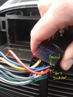
- Lastly, there is a Red wire that suddenly connected to nothing on the cars wiring harness and Here is what actually is most peoples issue
That red wire (on stereo harness)is the 12v Switched feed

