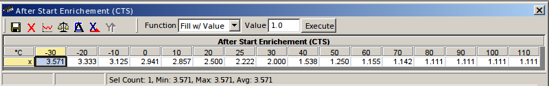
Technical Woj's turbo project

Currently reading:
Technical Woj's turbo project

Found the after start enrichment table :D It was right under my nose, only the values in it are so extreme that I was not paying attention to it. Can anyone explain to me why it needs to be so drastic (double the fuel at relatively warm engine conditions, almost quadruple it when really cold) for the factory 1.1 MPI engine? Note that this is over the regular cold engine fuel enrichment, which in itself adds a lot already...
 

Attachments

  • after_start_enr.png
    after_start_enr.png
    18.7 KB · Views: 88
Last edited:
No worries, I will get it somewhere (y) But I am almost certain that in this car it will not be my permanent ECU. What follows is that I will probably not get the car to the dyno with this ECU. But I want to master it to the point of being sure I can use this ECU with no problem on another project, if any.

The problems I had with the fuel made me study the program a bit more. Earlier I found the after start enrichment, now I also see how the load delta enrichments work. Earlier I assumed that whatever settings are there they would just work, but now this means I can start correcting chocking on acceleration if correcting the main VE map does not help (and so far it seems that's indeed the case). Only it is tricky - one map has to be done on cold engine, kind of difficult to keep driving and testing the behaviour and keep the engine cold :D Probably dumping an industrial size bag of ice in the engine bay and dropping some cubes in the expansion tank would help :D.

And, I also checked the values of after-start enrichements of the 18F ECU, they are way way smaller, at -40 degrees CTS it uses 217% of the default fuel, not ~350% :eek: Small valves in the 1.1 MPI engine not allowing all the after start fuel to get into the cylinders, or what?
 
I am getting somewhere. I am almost there with the startup and warmup enrichements, now I have found what tickles it, it now only needs to be fine tuned.

I also know what the chocking on acceleration (changing gears to be precise) is looking at the logs and thinking about it. It is very aggressive fuel-cut strategy (engine braking), see the picture. I do not think this is intendend and I suspect this is because of the lack of speed sensor - the ECU does not know that the car is moving and perhaps assumes a different, more aggressive, strategy for fuel cutting on closed throttle. One thing I will have to look into. When cold it is very OK right now, but as soon as it gets warm and fuel cutting is enabled the car becomes a bit undriveable (I even stalled it once on lights today :eek:). It is probably as simple as finding the parameter for delaying the fuel cut, only it needs to be found...

Another thing is that this ECU does not deal well with my emulated narrow band lambda signal from the AFR module. This can be clearly seen in the second picture, it floats like a boat. I might have to invest in a narrow band sensor (that died on me some two years back and since then I use the emulated signal).
 

Attachments

  • fuel_cutting.png
    fuel_cutting.png
    18.2 KB · Views: 65
  • floating_afr.png
    floating_afr.png
    16.9 KB · Views: 51
How did you go about making it handle a MAP sensor with a different range? I have tried that before... It wouldn't work well for me (the ECU would cut off fueling after about 5 seconds, with a "safety cut-off" error being given).
 
Oh, that part was actaully quite simple - there are two conversion values c1 and c2 that lineary convert voltage to mbar, you only need to know the electrical characteristic of your MAP sensor. If you are planning on keeping the same pressure ranges (that is, not going boost) this is sufficient. When boosting you also have to take care of switch off (there is a single switch for that) what I called "MAP sensible check" which checks with the current running conditions and sensors that the MAP value makes sense. In particular, if you boost it will assume the standard atmospheric pressure and kill all your efforts to make ECU know about the more interesting part of air pressure :D

Rethinking the fuel cut problem - it might be as simple as ECU assuming that the throttle is still closed for small values of throttle opening, so essentially calibration of the throttle position sensor is off. It would explain me stalling the engine when taking off on the lights...
 
From what I have seen back in the day, I believed it was due to the fact that the OE MAP sensor starts measuring at 10kPa, and the one I was using starts measuring at 20 kPa. Somehow the car knew that the voltage values output by the new sensor were lower than expected, and just shut it down.

If this is the case, it could be solved by changing the said parametrization. I must check if I can find out where those are, maybe I'll still fiddle with it a bit.
 
Starting up is way better.

But something is wrong with fueling, I calibrated the TPS a bit like I thought it would help and it got drastically worse (but I am not sure these two are related), the car was very jerky at moments, once it killed the engine while driving almost steadily. Something is amiss, I do not know what, can be something mechanical / electrical...
 
No, no, this is stock speed-density (well, sort of) algorithm based on MAP readings. It I were attempting to run on TPS I would not be comlaining that it does not work, but rather tearing my hair out trying to make it do something sensible.
 
It now stroke me what else could be a problem and this is not going to be easy :bang: Quite a chance is that it has to do with bad cam sensor signal and injector synchronisation. This would explain a lot, if not all of the problems I am experiencing... The simplest test would be to disconnect it and see what happens, but otherwise I am for the moment clueless on how to solve the problem if this is indeed it (given that it is a home made contraption).
 
I don't know exactly *what* you're working with, but I encountered the same problems with my 16V swap. The engine jerks around quite a bit at ~ 2000 RPM. Above it, it works great, and below it is acceptable, but there's several jerking at 2000RPM and the car often stalls when cold and idling.

I'm not running cam sensors in either the Seicento (with an 8V) or the Punto (with the 16V swap). Therefore I would rule out cam signal as being the cause of it. Maybe it's just bad fuel timing...
 
  • Like
Reactions: woj
You might be right - once synced the ECU should be able to stay on with the right injector phase. And some ECUs (for example 49F) actually do not use the cam sensor, just try to "shoot in" so to say.

However, it has come to my attention (thanks to PL forums) that the crank position sensors are not the same on the MPI Sei and SPI Cinq (what I use). What I have been told the MPI one has ~1200 ohm resistance vs. 800 ohm of the Cinq sensor. What would also suggest that his might be is the temperature behaviour - when warm it starts to be problematic - a common CPS symptom...

Now, the question is (I know little about VR-type sensors) - would it be simply sufficient to solder in ~400 ohm of resistance in series on one of the CPS wires...?
 
I will try to do it in my ECU converter plug (if the required wire is still accessible). But my fear is that it is not only about resistance, the other sensor might simply be such that it provides stronger signal or something. But in this case an option is to just try a different properly "ohmed" sensor and see if it also works with my old ECU (just checked - new one is 27 Euros plus postage in NL, perhaps worth the risk).

I could try several things, but hall sensor for crank is not one of them. The car is actually for sale and I need to have it cleanly running with the old setup upon request. So no risky mods that would put it on stands for weeks or months.
 
(if the sheilding remains in place).

And now that you have mentioned this - this is another thing to look into, I kept (obviously) the shielding installation I always had, the shield is connected to the ECU mounting leg I believe. In MPI Sei the shielding for each sensor is connected to ECU pins. I now wonder if that might have anything to do with anything...
 
I would say hall sensor would not cause that, even with a slight deviation in resistance value... And this is because the signal from the said sensor is interpreted as a square wave by the ECU, and therefore is not so much sensible to resistance as it is with noise.

But... It can't harm to try! I know I'm still using the original sensor for this ecu, so I ruled that one out.
 
But I do not have a hall sensor!

I think I will start with the basics - it might be as trivial as my shielding connector not having enough contact, I kind of bodged it, it now has very little of the mating surface. I hope it is that trivial...
 
Back
Top