Roof mounted intercooler?


You are using an out of date browser. It may not display this or other websites correctly.
You should upgrade or use an alternative browser.
You should upgrade or use an alternative browser.
Currently reading:
Technical Woj's turbo project
Sequential injection?
") The IAW 4AF ECU is going to be in there, plug and play. I am very far in with this, but I don't think I will finish before X-mas (I am a bit lagging with software side).
The IAW 4AF ECU is going to be in there, plug and play. I am very far in with this, but I don't think I will finish before X-mas (I am a bit lagging with software side).Attachments
Conversion plug finished, the loom in the car fully preped too. A fresh ECU off fleabay all soldered up inside (small mods necessary for what I want to do). Mechanically everything is ready, only the software remains to be finished This is small hours away, unfortunately ones yet to be found...
This is small hours away, unfortunately ones yet to be found...Attachments
Have been finishing the ECU software and I think I have succeeded and tested it all I could on the bench. At this point I also owe big thanks to Mr. Honeymonster for helping me out tremendously without even knowing it with this post:
https://www.fiatforum.com/members-motors/300150-monster-cento-ecu-master-thread-2.html?p=3036381
Before I found it I was fighting for two full evenings with the calibration values for these two :bang:
Now I need to test it on the car - might happen on Friday (lots of shaky conditions have to be met), but there will be no driving, just start up, idling and reving. If this is successful I will spill out some technical details of how to make the conversion plug, but for now I do not want to jinx it. Also have to finish the PC-side custom diagnostics software, but this is now piece of cake (just dull Java coding).
https://www.fiatforum.com/members-motors/300150-monster-cento-ecu-master-thread-2.html?p=3036381
Before I found it I was fighting for two full evenings with the calibration values for these two :bang:
Now I need to test it on the car - might happen on Friday (lots of shaky conditions have to be met), but there will be no driving, just start up, idling and reving. If this is successful I will spill out some technical details of how to make the conversion plug, but for now I do not want to jinx it. Also have to finish the PC-side custom diagnostics software, but this is now piece of cake (just dull Java coding
).Quoting Mr. Borat: "Great success!" The engine started up on the first attempt, however, not without struggle. This is because I am off by about 13% with the fuel and it is running lean as the AFR display showed me. But considering how lean it is it managed to keep up a very nice idle (I am certain that the batch injection system with this AFR would not be able to hold that cold engine running with this fuel). Another good thing - no MIL complaints whatsoever. But that's on the dash. The bad thing is that I managed to mix up the diagnostics cables inside the cabin (I flipped the K and L line wires, I already checked that, I have no idea how I could have made a stupid mistake like this :bang and I was not able to check the diagnostics, nor I was able to quickly rectify the fueling issue and upload a fresh version of the program. And since this was just a quick try with my 2-year old on the lap I had to give up for now. Another thing to rectify is that part of the loom going out of my conversion plug is routed a bit unfortunately and the MAP sensor bracket stands in the way. But this can also be fixed in a couple of minutes. The videos:
The engine started up on the first attempt, however, not without struggle. This is because I am off by about 13% with the fuel and it is running lean as the AFR display showed me. But considering how lean it is it managed to keep up a very nice idle (I am certain that the batch injection system with this AFR would not be able to hold that cold engine running with this fuel). Another good thing - no MIL complaints whatsoever. But that's on the dash. The bad thing is that I managed to mix up the diagnostics cables inside the cabin (I flipped the K and L line wires, I already checked that, I have no idea how I could have made a stupid mistake like this :bang and I was not able to check the diagnostics, nor I was able to quickly rectify the fueling issue and upload a fresh version of the program. And since this was just a quick try with my 2-year old on the lap I had to give up for now. Another thing to rectify is that part of the loom going out of my conversion plug is routed a bit unfortunately and the MAP sensor bracket stands in the way. But this can also be fixed in a couple of minutes. The videos:Attachments

So let me say a couple of things. The main purpose of this ECU project is to fire up my engine with the turbo reprogrammed IAW 4AF ECU. The baseline assumptions were (a) minimal modifications of what's already in the car and (b) plug and play functionality so that I can revert to my old ECU setup within minutes. The 4AF comes from an MPI Sei and have these major advancements over 18F: full sequential injection, knock sensor control, vehicle speed sensor, ECU controlled rad fan operation (not sure this is an advancement though , and two lambda sensors OBD2 compliant fuel control plus diagnostics.
Obviously, my Cinq is not ready for all this as it stands, but since I have almost full control over the ECU I simply kept my setup as is and essentially only went for sequential injection and knock control. Everything else is simply turned off in the program. At this point what I needed is cam position sensor, knock sensor, separate injector wires, and the need to account for a couple of design differences between the electrical systems of the two ECUs.
Injector wires were easy - my setup is already MPI and one midway 4-way plug in the loom to reconnect between the two ECUs did the trick. (BTW, Super-Seal plugs rock.)
Knock sensor just screws on the block, simple, but unfortunately there is no properly placed bung on my block. At the moment it is screwed on "nearby" and this will require sensor setup changes in the ECU I believe, something I am not yet sure I can do right. There is also a more suitably placed bung, but with a larger thread - will need some "adjustments".
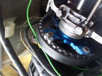
Cam position sensor required most work. I drilled and tapped the cam wheel and screwed (M3 screws) on two ring magnets (South pole) and mounted a generic Hall sensor (will provide a link later) under the cam cover on a (bodge) alu bracket. According to my calculations one ring magnet should be sufficient, however, its position would have to be estimated with much more precision.
Finally, the electrical differences. 4AF takes its power differently. The constant power is fed directly from the battery through a 7.5A fuse (in 18F through self controlled power relay). Then there should be ignition switched power feed directly to the ECU which in 18F is disconnected (as opposed to 16F, the so many times discussed issue of ECU pin 26). Last thing in 4AF is the separate dash rpm signal which in 18F/16F is fed on the same line as fuel relay control. In 4AF these have to be separated.
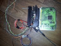
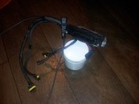
Based on all this I made a couple of entry points in the car's loom and a convertor plug out of a to-be-bined fried 18F ECOL ECU and a spare complete 4AF loom (not easy to get, luckily there are still good folks out in the world). What needs to be connected to what comes in the next post when I will be on a PC.
, and two lambda sensors OBD2 compliant fuel control plus diagnostics. Obviously, my Cinq is not ready for all this as it stands, but since I have almost full control over the ECU I simply kept my setup as is and essentially only went for sequential injection and knock control. Everything else is simply turned off in the program. At this point what I needed is cam position sensor, knock sensor, separate injector wires, and the need to account for a couple of design differences between the electrical systems of the two ECUs.
Injector wires were easy - my setup is already MPI and one midway 4-way plug in the loom to reconnect between the two ECUs did the trick. (BTW, Super-Seal plugs rock.)
Knock sensor just screws on the block, simple, but unfortunately there is no properly placed bung on my block. At the moment it is screwed on "nearby" and this will require sensor setup changes in the ECU I believe, something I am not yet sure I can do right. There is also a more suitably placed bung, but with a larger thread - will need some "adjustments".
Cam position sensor required most work. I drilled and tapped the cam wheel and screwed (M3 screws) on two ring magnets (South pole) and mounted a generic Hall sensor (will provide a link later) under the cam cover on a (bodge) alu bracket. According to my calculations one ring magnet should be sufficient, however, its position would have to be estimated with much more precision.
Finally, the electrical differences. 4AF takes its power differently. The constant power is fed directly from the battery through a 7.5A fuse (in 18F through self controlled power relay). Then there should be ignition switched power feed directly to the ECU which in 18F is disconnected (as opposed to 16F, the so many times discussed issue of ECU pin 26). Last thing in 4AF is the separate dash rpm signal which in 18F/16F is fed on the same line as fuel relay control. In 4AF these have to be separated.
Based on all this I made a couple of entry points in the car's loom and a convertor plug out of a to-be-bined fried 18F ECOL ECU and a spare complete 4AF loom (not easy to get, luckily there are still good folks out in the world). What needs to be connected to what comes in the next post when I will be on a PC.
Last edited:
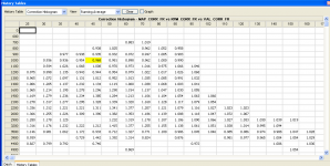
Played with it a bit more and made a bit more serious runs today. In principle everything works (but one thing), made a succesful calibration procedure and there are no DTCs in the ECU. But calibrating the fuel is not easy with this ECU. I have defo lean spots and also rich spots in the VE table, making small changes seems to flip everything upside down. Also it still struggles when very cold and it somehow instists on having the fuel lean when cold, despite all the necessary corrections being in effect. So in essence, the fuel is not consistent through the temperature range, but it should be (the maps are based on the factory maps for the same kind of engine). All this without narrowband lambda correction, with the correction the fuel is quite stable when warm but then it is difficult to see where the holes in the VE table are because the ECU evens everything out.
The downsides and things to correct. The calibration values for the AFR signal I got from my module's documentation are off for rich regions by ~0.5 AFR. This causes the ECU to see wrong AFR and giving me false reports as to how far the fuel is off (but I also see it on the display).
But more importantly - my procedure for on-the-fly fuel correction based on AFR signal is not working. I made a naive (purposely) implementation (not a PID controller) and it is a no go. On the first attempt the correction killed the fuel instantly. After realising the core of the mistake I modified the procedure a little bit and it managed to actually correct the fuel but it started "waving" it and in the end killed the engine again. I believe it can work, but setting up the parameters is going to be a pain. I might have to think about twisting the factory lambda correction procedure to use my AFR signal somehow...
I have some clips, maybe I will upload them a bit later.
Some clips and a log of reported fuel corrections that would be required to hit the target AFR, easy to see that it is nowhere near perfect yet.
Also, the EBC code seems to work fine too, but I did not test it thouroughly, running on boost was occasional.
Also, the EBC code seems to work fine too, but I did not test it thouroughly, running on boost was occasional.
Attachments
Managed to contain the fuel and it essentially runs fine, I simply found a quick way to look up ECU's full autocalibration table (which is actually quite dense, 8x8) and corrected the fuel based on that. Fuel on full boost is also spot on (second video). Also managed to figure out the problem with cold start up and warm up. With this cam this engine needs much higher idle revs than the factory setting for 1.1 MPI. I copied the idle settings from my 18F ECU and it is considerably better (first video).
However, I still do not like the tick over, it sounds very rough (not audiable on the video, the crappy sound is stuff in the door's side pocket) and the AFR is unstable (has very lean spikes, only visible on the AFR display, watch the first video carefully). This makes me wonder if there might be an issue with (one of) the injectors. If they are not spraying evenly, or they have the wrong spray pattern, then in full sequential mode this would manifest itself quicker and harder than in batch mode. Another possibility is something wrong with the cam sensor synchronisation, but I believe that then the ECU would tell me something about it.
Further developments are on hold for at least a week
There is one more possibility for having issues with idling and fueling in general. I just looked at the factory warm up enrichment maps. They target the stoich 14.7 AFR already at 10 degrees Celcius of coolant temperature (and also then the lambda correction kicks in) . This moment can be witnessed in the first video. So I checked what the 18F enrichements do and they actually put much more fuel in at these temperature range and the enrichements actually last until 60 degrees Celcius or so. I already corrected this now, but I will not be able to test it very soon I have no idea how the factory enrichments manage to keep the 1.1 MPI engine running smooth at cold conditions - probably because of higher CR and much less aggressive cam...
. This moment can be witnessed in the first video. So I checked what the 18F enrichements do and they actually put much more fuel in at these temperature range and the enrichements actually last until 60 degrees Celcius or so. I already corrected this now, but I will not be able to test it very soon I have no idea how the factory enrichments manage to keep the 1.1 MPI engine running smooth at cold conditions - probably because of higher CR and much less aggressive cam...Despite my thinking I would not have time until the weekend to play with it again I managed to squeeze some time today. I am getting there with the regular running fuel, it has still lean spots and jitters there, but I am progressively removing those and looking at the autocalibration values the ECU is getting more and more happy about the fuel. Starting up is still an isse - it is heavily overfueled during the first seconds of running and struggles. I looked at the program again, found another map that (I believe) is reposnsible for right after start up enrichement which is injector size dependent and also needs rescaling. Will try that at the next possibile time slot. If that's not the reason then I am getting slightly lost...
One thing I noticed (but perhaps I am wrong, there were too many things happening to watch everything at the same time) is that the turbo spools faster. Is that possible, anyone having explanation for that? Could sequential injection provide that better mixture and burning of it that the engine is more efficient at lower revs?
One thing I noticed (but perhaps I am wrong, there were too many things happening to watch everything at the same time) is that the turbo spools faster. Is that possible, anyone having explanation for that? Could sequential injection provide that better mixture and burning of it that the engine is more efficient at lower revs?
well as usual its all a bit beyond my knowledge so not got anything useful to add but still here, following with great interest. Nothing but respect for the level of tinkering going on.
If you have bigger injectors then the fuelling could be off quite a bit. Low compression wont help.
There should be a start fuel pulse table with reference to temperature and linked to the main fuel table. Once the main fuel/ignition maps are setup, the cranking and idle should be easier to do. Idle and high idle targets may need adjusting
I still have to adjust mine as it is over fuelling at cranking and enrichment is out also now the cold weather is here.
As for the turbo spooling quicker.... Maybe you have a partial launch control setup? Lol
In IAW 18F it is indeed like this - CTS scaled map for cranking pulse and then the main fuel maps with enrichements and all take over. Here it seems it is a bit different - looks as if there is one more step before the main maps take over. Will figure this out. Once in main maps accounting for bigger injectors is dead easy - there is actually a separte variable (as it shoud be in every decent ECU program) that defines the size.
As for the compression ratio - not sure what you mean by "won't help". I noticed that with the IAW 18F ECU the engine starts very easily. So easily that my healthy factory t-jet in GP seems as if it has a dead battery comapred to my Cinq. But there is defo an interplay between low compression ratio and the voltage level during cranking - since the engine is easier to turn the voltage does not drop so drastically and in effect the injectors give more fuel (quikcer opening).
Launch control - I do have one, but it is disactivated, it needs a speed sensor which is not there for the moment.
As for the compression ratio - not sure what you mean by "won't help". I noticed that with the IAW 18F ECU the engine starts very easily. So easily that my healthy factory t-jet in GP seems as if it has a dead battery comapred to my Cinq. But there is defo an interplay between low compression ratio and the voltage level during cranking - since the engine is easier to turn the voltage does not drop so drastically and in effect the injectors give more fuel (quikcer opening).
Launch control - I do have one
, but it is disactivated, it needs a speed sensor which is not there for the moment.If anybody wonders why I write all this - it is mostly a log for myself
What I though was the after start enrichment map is not - but I think it does define the time of after start enrichement. And today I have found maps that are more likely to be what I am looking for, and moreover, a single switch to kill all those enrichments with one button press, this will make testing it much easier.
I also messed up with lifting up the CTS threshold for lambda correction - the ECU still insisted on turing it on at 15 degress Celcius of coolant temperature. But now I know what I messed up, will try again tomorrow I hope.
And then - I keep correcting the main VE table, the ECU is more and more happy (internal logging wise) about the values, but the engie still jitters like hell at certain points. Now it makes me think it might be the same issue I had with 18F for a long time - the heavy enrichment caused by charcoal canister operation and corresponding panic attempt of the ECU to correct the fuel down which settles down only after a longer moment. If I keep getting these problems I have a way to kill the canister operation altogether that I can try out.
The fuel on boost is very sufficient, but here defo overfueled in some places. Today at moderate boost levels I was seeing the AFR of ~10 on the meter, that is too much. This is not fixable without a (pricey) steady-state dyno visit.
More of an observation - this ECU seems to use the ignition more to control the idle speed. The effect is that less air is used (the MAP is lower than with 18F, though only about 1-2kPa) with more ignition advance to keep the idle speed at the required level.
The project is not going to where I want it to be. Today I was thouroughly testing what is happening with fuel on startup. What I saw is that ECU reports, through diagnostics, 10ms of injection right at the beginning of engine start. This is defo too much (time I expect to see somewhere near entering boost for these injectors), but I do not see where it is coming from in terms of map data.
While uploading another version of the program during those tests something went wrong with the cable and it had to be restarted (that in itself is not a problem, I can totally boot strap the complete software). But now the ECU is not responding to normal operation, the pump or MIL do not come up. I reloaded the complete program, nothing. So I took the ECU and the whole installation out to deal with it at home with my test equipment. After that I realised I should have also tried reflashing the EEPROM (a while back I tested what happens when it is messed up - the ECU does play dead). This can be either of the three - EEPROM messed up, something fried in the ECU, electriacal fault in the conversion loom (I am not 100% confident about my soldering). In any case, the car is healthy - I have put the old ECU back in and everything works, went for a short drive and...
... this brings me to the last thought for today - I am nowhere near the smoothness and driveability of the 18F ECU with this 4AF project yet. My old ECU is just a charm - clean, beatiful startup, smooth warmup, driving, acceleration and full abuse. Just like you would expect from a factory setup. Either I did an outstanding job with this old ECU, or I am not doing it right with the new. In any case, I lost a bit of motivation, why would I sit in the car and do endless startup tests and other things with this new ECU, while I could be spending the same time kicking the s**t out of the engine and the car with the old ECU
Hey man just think of how good it will be. I am hyped and worried if my car will be on the road for monday if not I will be walking for a week. But hey it's all about learning new stuff right?
Yeah, the point is I am not sure that it will be that good. So far it is not meeting my expectations...
Anyhow, the good news is that the ECU is alive, and so it seems the conversion plug - both worked in my "laboratory". This means that something went wrong when interacting with car's loom... probably a missing feed somewhere or something. No clue for the moment.
I moved my search for this extra start-up enrchiment to be workbench, it is much quicker, but so far no results Equipment shows me it is only momentary, very short (~1s no more), but apparently long enough to cause flooding for some seconds.
Anyhow, the good news is that the ECU is alive, and so it seems the conversion plug - both worked in my "laboratory". This means that something went wrong when interacting with car's loom... probably a missing feed somewhere or something. No clue for the moment.
I moved my search for this extra start-up enrchiment to be workbench, it is much quicker, but so far no results
Equipment shows me it is only momentary, very short (~1s no more), but apparently long enough to cause flooding for some seconds.