Good news.. ")
Do keep that jumper cable nearby though
Do keep that jumper cable nearby though


Hi user77
I don't know your level of electrical expertise, so if what follows sounds patronising I apologise in advance ! The figures I give are just for illustration of what your problem might be.
I think we can assume from the story so far that your battery is healthy and its voltage hardly changes when a big current is drawn. Let's say that somewhere else in the feed or return from the battery there is an unwanted resistance of 0.02 ohms. Doesn't sound much, does it ?
When you first turn the key, the engine management and various other things will draw current through this resistance. Let's say the drain is 10 Amps. The voltage dropped across the resistance will be 10 x 0.02 = 0.2 Volt. So anything downstream of the resistance will get battery voltage (12.5 V) less the 0.2 V drop which will be 12.3 Volts. Things like the dashboard and Engine management will be quite tolerant of this slightly reduced voltage and will appear normal.
Now turn the key further, to the start position. The starter solenoid plus starter motor will draw a very high current, say 300 Amps. The voltage drop across the 0.02 Ohm resistance will now rise to 6.0 Volts, so anything downstream will only get 12.0 - 6.0 = 6.0 Volts (I've allowed for the battery volts to dip a little to 12.0 with this big current). Now, 6.0 Volts isn't enough for the dashboard, engine management etc and they will go dim/go out/make funny noises etc. The starter motor will seem sluggish, and will only crank the engine slowly.
It seems to me that your battery is OK. The large capacity of a Ducato battery should be enough to withstand the small parasitic drain from things like alarms and cameras for many days, not just hours or minutes. It's just not possible to quickly drain a battery of this capacity in a short space of time unless you have a substantial current flowing. If the battery is OK, you need to look elsewhere.
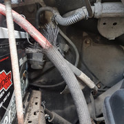
I think the only way to pin this one down is to scrutinise every joint in the starter current path, from the positive battery post all the way to the starter and all the way back back again to the negative post. This might involve dismantling and cleaning. Bear in mind that bad joints can be sensitive to vibration, and can seem to mend themselves for a while.
If you wan't to be more scientific about it, the sort of unwanted resistance (0.02 ohms) needed in the starter current path to give your fault symptoms is pretty small, and way below the measurement capability of normal ohmmeters and continuity checkers. However, one way you can roughly measure this sort of low resistance is to put a sensitive voltmeter across one of the joints/cables/fuses in question and then turn on an electrical item so as to get reasonably big current to flow through it. Headlamps will draw about 10 Amps, the Cabin Blower up to 25 Amps on full speed. This doesn't apply to the parts that only serves the starter motor, but is applicable to the common parts of the positive supply and earth return. Divide the Voltage Drop by the current in Amps and you will get the resistance, e.g. 0.1 Volts drop with 25 Amps is 0.004 ohms. Although 0.004 seems like a tiny figure, it is still probably still more than it should be for a substantial bolted joint.
I am curious that putting a battery booster on gives an instant start. Are both the booster's cables being connected directly across the vehicle battery, or to somewhere else ? If the latter, it's possible that the troublesome joint is not in circuit as far as the booster is concerned.
Separate reply re Alarm.
If you cut the wires off, these two circuits will be broken. So you need to bridge them to retore normality.
See if you can probe the relay box with a continuity checker, to see which two pairs of wires are linked by the relays. They will not have any resistance reading to any other circuit. This should give you the colours you need to join together outside the box to retore operation.
Separate reply re Alarm.
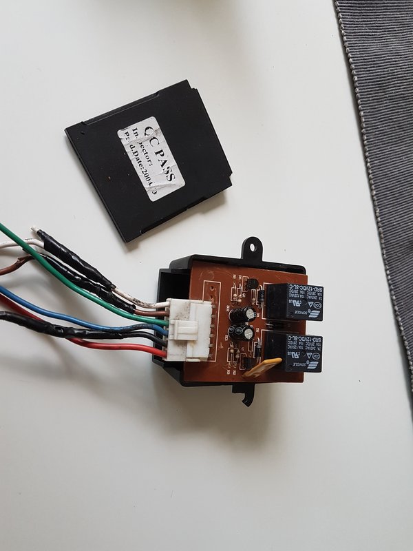
Yes, the box looks like an aftermarket item.
It's likely that the two relays are wired so that two separate circuits (one is likely to be the fuel pump) are interrupted if the alarm goes off. The rest of the time the relay contacts will be closed and the two circuits will work normally.
If you cut the wires off, these two circuits will be broken. So you need to bridge them to retore normality.
See if you can probe the relay box with a continuity checker, to see which two pairs of wires are linked by the relays. They will not have any resistance reading to any other circuit. This should give you the colours you need to join together outside the box to retore operation.
From eLearn the pump and fuel gauge harness seems to connect into the main harness below the ECU. The pump supply is controlled by the ECU via a relay in the engine bay fusebox, and the return is via the inertia cut off switch near the battery - more accessible for extra wires. For reference the fuel pump supply wire is brown on pin 4 of connector D145, and the negative pump wire at the inertia switch is white/black on pin 3. (According to eLearn, which has many errors.)
My remote central locking is only via after market alarm fob on a sequential push basis, or from physical door key. No buttons on Fiat fob.
Communicator,
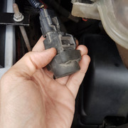
I did move the inertia switch around. As a matter of fact, it was dangling down freely from its wires, so I picked it up to see what it was and then I noticed the rattling noise inside.
I removed the rubber cap on the switch and I saw a white plastic cage with a metallic ball inside. I decided to just wire it back up after removing the alarm wires and leave it be.
Will this bring the fuel pump back online? It remains to be seen.
The correct position for the inertia switch is, firmly mounted vertically on the bulkhead near the battery, with the cap upermost.
=========================================================
Exactly the same here. No buttons on the fob and central locking only via the alarm fob OR the door key. I just thought that an alarm system wouldn't be including a full-on central locking system to replace manual locking on a car. If the central locking is indeed an aftermarket add-on it would explain why the wires running to the doors don't look factory jobbies.
You have misunderstood this. The central locking is the facility whereby all doors lock when for instance the driver's door is locked. The remote facility augments this. I suspect that your box is an interface between the remote control via the alarm system and the vehicle circuitry. If all doors lock as above your central locking is OK, but you will have lost the remote facility via the alarm. May I suggest that while perhaps inconvenient, this is secondary to keeping the vehicle moving.
========================================================
Any thoughts on the wiring connections of the interface box?
EDIT: If we accept that this box controls the central locking, it would explain why the white and brown wires were spliced with the alarm.
It may be that RED brings 12v, BLACK is the ground and then WHITE and BROWN are there to activate the relays, which in turn route power to the GREEN and BLUE wires to lock/unlock the doors.
This is similar to what I would expect. I have never had cause to delve into the central locking, and in my opinion the aftermarket alarm system connections on my vehicle are a mess. What is required is to take the lock and unlock commands from the alarm system receiver, and interface them to the lock and unlock command wires from the door key locks. There should be no need to supply power directly to the door locking motors, or to run wires into the doors.
========================================================
Regarding power supply, there is no yellow button to press in the fusebox. I'll try to take a pic also JIC.
You have misunderstood this. The central locking is the facility whereby all doors lock when for instance the driver's door is locked. The remote facility augments this. I suspect that your box is an interface between the remote control via the alarm system and the vehicle circuitry. If all doors lock as above your central locking is OK, but you will have lost the remote facility via the alarm. May I suggest that while perhaps inconvenient, this is secondary to keeping the vehicle moving.
=========================================================
About the battery booster, I am always hooking it up directly to the battery; I leave it running for a few minutes and then the car starts fine.
========================================================