Technical Seicento MPI Turbo ECU

Currently reading:
Technical Seicento MPI Turbo ECU

So, a small heads up ;) The first fully working version of the turbo program for IAW 4AF is ready. This includes:

- full boost understanding and corresponding high resolution maps for fuel and ignition

- disabling of charcoal canister operation when in boost (so that no mechanical contraptions are be needed to prevent the turbo blowing air into your fuel tank :D)

- boost defender ignition cut, mappable to RPM

Other things in control not really related to turbo, but worth mentioning are: presice injector size control, precise MAP sensor characteristics control, killing almost any kind of complaint the ECU might have (including missing lambda(s)), switching off fuel autolearning, killing the need to do RPM wheel learn, setting idle engine speeds. And lots of other things :devil:

The thing that is not there yet is Electronic Boost Control. It is next on my todo list, will get you posted ;)

No pictures or movies to show :( who would be interested in a big cabling mess, a bunch of diodes flickering, and an LCD displaying numbers only I understand :D
 
You pervert :p Perhaps I will do something in the future to satisfy your needs.

In the meantime, I am now 99% certain there is going to be EBC in the ECU, moreso I think it will come cheaply - not only there is a free fast speed output pin available and connected to the ECU's connector, it already has a procedure implemented to produce arbitrary fill and frequency PWM signal. This cannot be better :D

There are also two input (on/off) pins available, but these required minor soldering (easy-peasy, something I did in 15 minutes, did not burn the ECU or myself, and that included desoldering the necessary components from the broken ECU). That means two dashboard control switches. One for selecting boost maps. The second... I am thinking launch control, when I find the variable that keeps the vehicles speed (matter of time) the launch control is going to be semi-automatic, that is, disabling itself after reaching some threshold speed. And once I have the speed indication I will have gear based boost correction.

Even if I do say so myself, I am impressed with how smooth this is now going, and start to wonder why would I ever need EMU or any other SA.

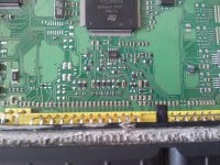
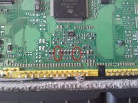
And to make Honeymonster's day, attached the picture of my soldering job (original size in case you need to magnify it). Can you spot what was soldered?
 

Attachments

  • 2013-09-22 16.56.10.jpg
    2013-09-22 16.56.10.jpg
    3.5 MB · Views: 66
I'd say in the following places, but very tidy work. :D

2013-09-22%2016_56_10.jpg

Once you've mastered this and it's relevant technology you really should consider making your own standalone. Maybe reverse engineer a few other manufacturers products to find the best bits and finally congeal all that goodness into one shiny home brew ECU. In the mean time keep up the outstanding work this is very impressive stuff.

For some strange reason I still want an

emu.jpg

though, it might just be the cool name. :D
 
Last edited:
In my defense for bad soldering cc1:

- this is a test/scrap ECU, I do not care much for it

- my really good pliers to hold on to tiny things are still buried somewhere in a moving box (for 2 years now)

- I still have not purchased proper pointy soldering tip for my iron, I use a screwdriver like tip

- last, the soldering position was extremely uncomfortable with the ECU deep in the table. Moving it to the front would require disconnecting the whole thing. This alone would cost me much more time than the soldering itself.

I would not write this if there was not another update: the PWM thing was a really really low hanging fruit. It is as easy as giving it a min and max DC fill, initial fill and frequency, pin orientation (normal or negated), and that is it, all nasty interrupt business and checking healthiness of everything is done by already existing ECU program, and my diode pulses as I want it to. At this pace the complete EBC thing should be ready in 2 weeks or so :D
 
Ive only just seen this thread.

This is incredibly impressive. An oem plug and play answer would surely be very desirable if the price is right.

I'd love to have a better understanding of the work you've put in!

Will follow with interest, great work.
 
At this point of the day, I'd love to have a better understanding of the things I am doing myself. Things are moving forward with incredible pace at the moment.
 
So Electronic Boost Control seems to work, I will try to post a video for Mr. Honeymonster tomorrow.
 
Good stuff, shame about the 480p lego brick resolution video. :D

So I take it your software adjusts map pressure and TPS simultaneously for testing?

Very tidy work with the wiring. (y)

Are you going to put all this in a nice project box or leave it breadboard for easy modification?

When's the first modified ECU (on a car) test?? :D
 
Good stuff, shame about the 480p lego brick resolution video. :D

I could do full HD, but I did not want to spend half a day uploading :p Besides, only found out later how crappy it came out :mad:

So I take it your software adjusts map pressure and TPS simultaneously for testing?

And RPM. It tries to emulate engine behaviours, load is settable, so that on one occassion pressinig throtthle to 90% will produce 3000 rpm and full boost, on another 7000 rpm and vacum.

Very tidy work with the wiring. (y)

Looks nice, but actually at least one wire is current overloaded I think, the RPM signal breaks off because of that from time to time. I'd need to sort it out, before I burn our place down.

Are you going to put all this in a nice project box or leave it breadboard for easy modification?

Every ECU requires different setup of things, and I am not planning to finish on this one :D The "car" board that you see though needs redoing, if I get round to it I'll try to make it more universal.

When's the first modified ECU (on a car) test?? :D

My car me thinks. But there are obstacles. One is that I need to change over the whole timing belt accessroy equipment to get cam sensor. The other is it would not be a 2 day project and I do not have a spare car (yet).
 
Wife would kill me if I bought a Seicento ;)

Anyhow, I am getting closer and closer to indeed have a practical stand alone out of this thing. Some things are yet to be tested to confirm, but:

1. There is a way to change the trigger tooth on the primary wheel. (Changing to some other wheel than 60-2 is very very very difficult). So there is a way to move the TDC around for the different engines. (For example 16V FIRE-s have them shifted by 3 teeth on the wheel with respect to 8V).

2. The firing order can be changed easily too.

3. The ECU has apparently the ability to do sequential spark (again, with easy configuration parameters), only the two extra drivers are missing on the board. I will try to solder them on from the spare ECU (and do a better soldering job than last time :p). Also coil dwell times are easily configurable.

4. The ICV stuff seems to be very self adaptive so can be probably left alone.

5. I can also now extend the diagnostics interface to log anything I want externally through ELM327.

I think I can dare to say that I should be able to drive a t-jet with this ECU very soon.
 
While I am at it - a quest for (or a confirmation of) an idea. I will also implement Launch Control. This in itself is now very easy, but I want to tell the driver somehow that it is currently on (so that he knows the engaging of LC was successful and that it is on until certain minimum road speed is reached). I was thinking about raising the idle engine speed to 2000 rpm... What do you think? I would prefer not to twinkle with the MIL for this, MIL is a MIL, should only announce things that are wrong and/or dangerous.
 
Brilliant idea, though, I am not yet sure if the immo light is brought on by the ECU or the immo box :confused: But I will find out :D
 
Back
Top