IMG_1874.JPG

Panda (Classic) My Sisley, Panda 4x4 - division north

Introduction

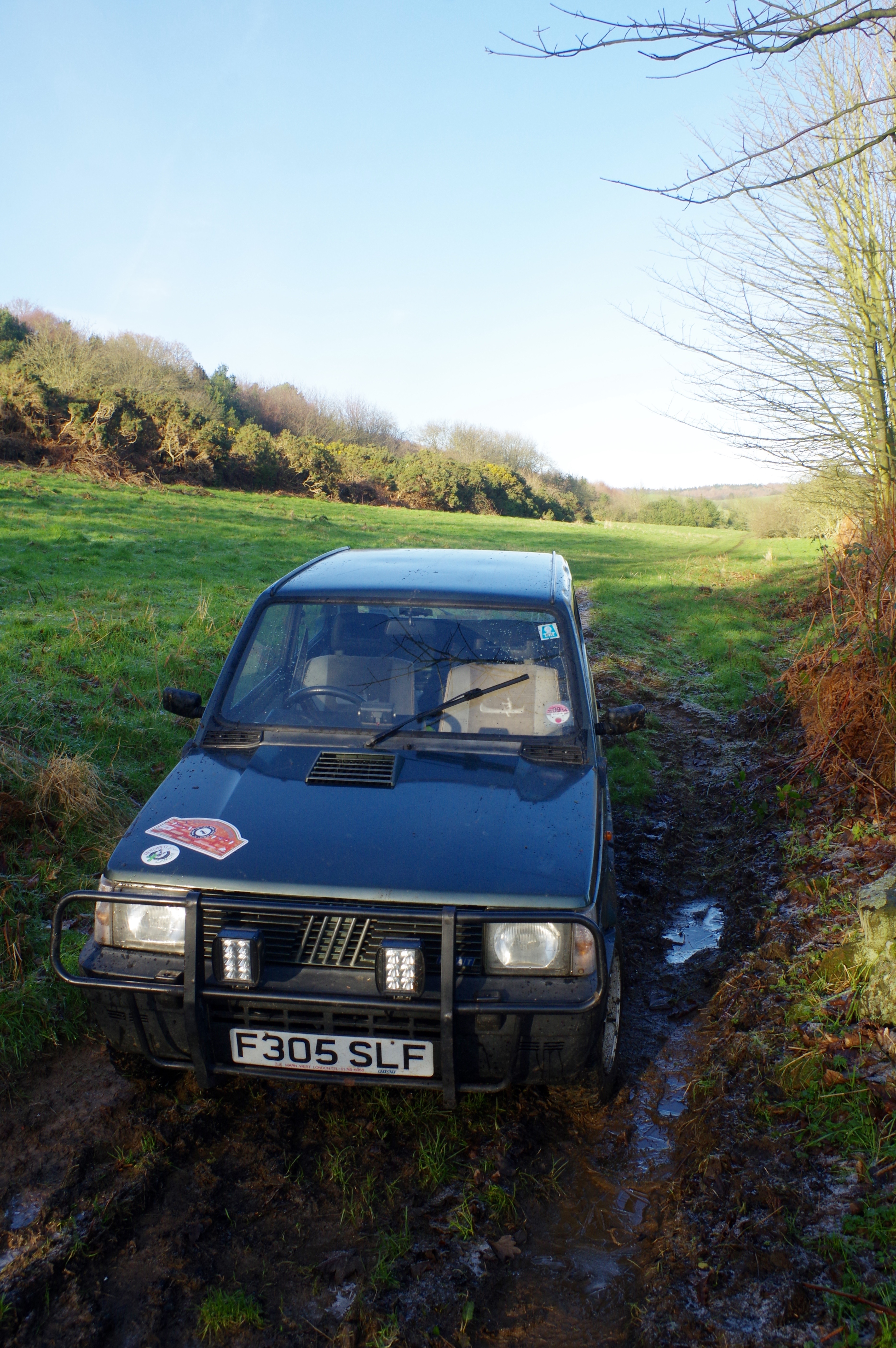
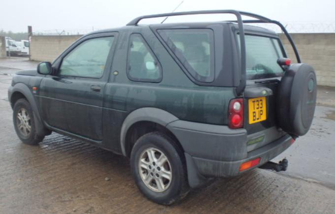
As mentioned before, I'm starting new thread for my recent purchease.
Bought it from forum user, deposit was place without seeing the car first, went all the way down south with rest of the cash and A-frame in boot.

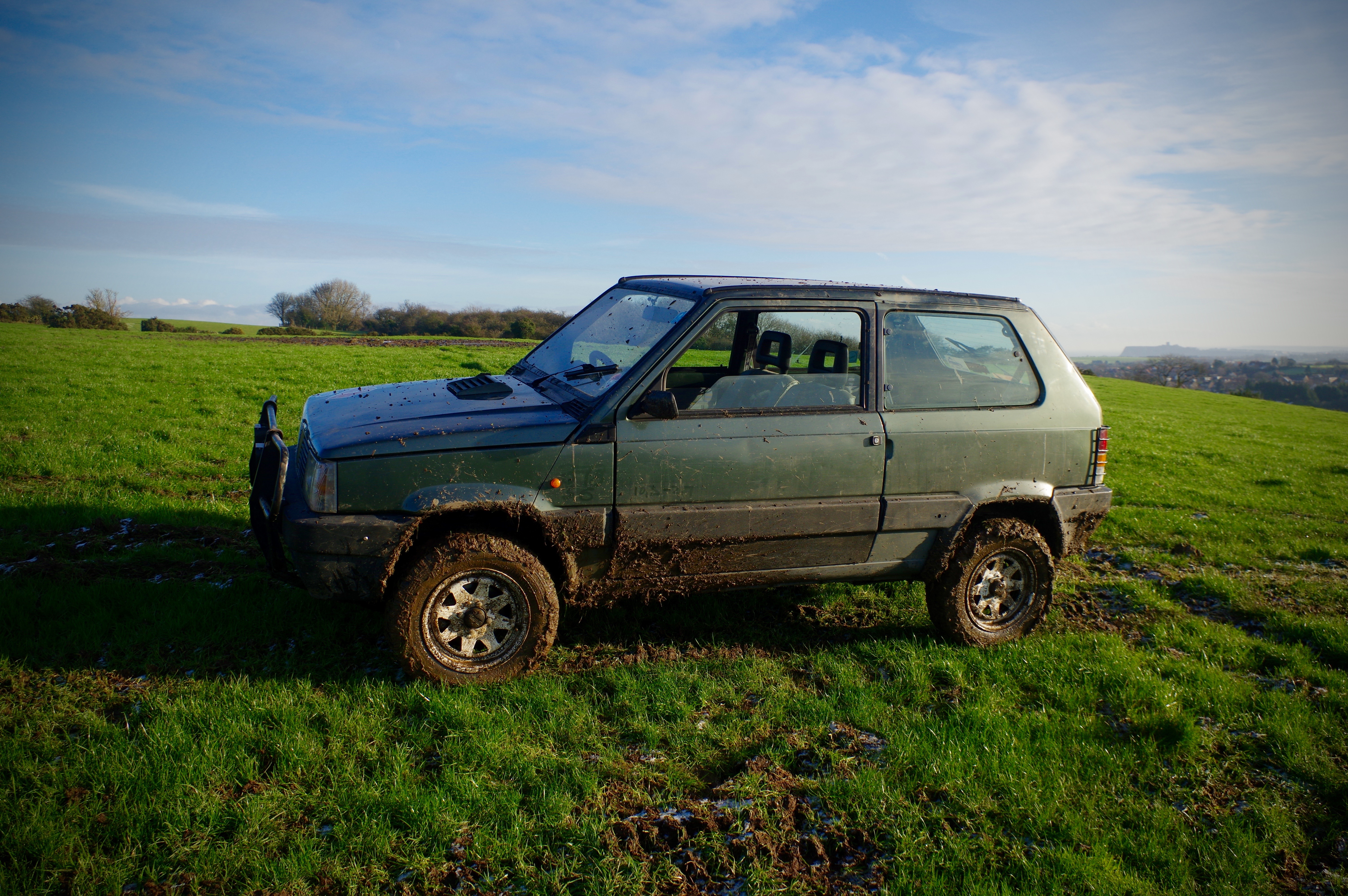
First summary of the car is ( 1 is very poor, 10 is perfect):

  • Originality - 6,
  • Bodywork - 7,
  • Engine - 6,
  • Gearbox - 5,
  • Interior - 5,
  • Structural rust - 8,
  • Visible rust - 8,
  • Previous owners maintain - 7
Plan for the car is to keep it road worthy and in good mechanical nick, join Panda 4x4 UK club and have some play with other Northern forum members.

As it is now, I'm not willing to make any statement what needs to be done as I had only spend about 2h last week by checking and looking at the car in more details way.

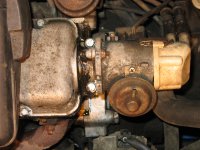
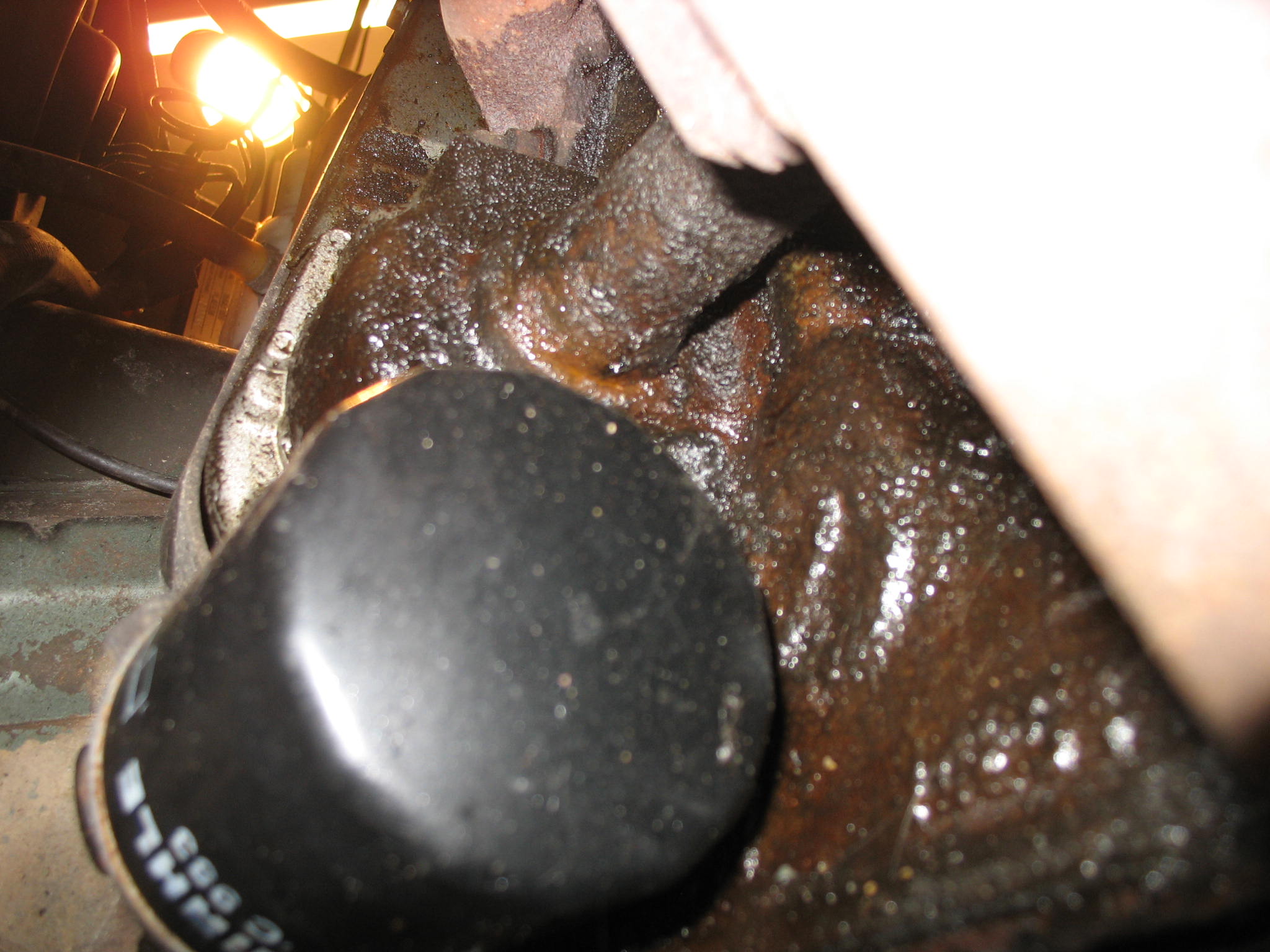
That is my bigger worry for now - bloody milky coolant and a bit of mayo under the oil cap.

IMG_18771.JPG

IMG_18843.JPG


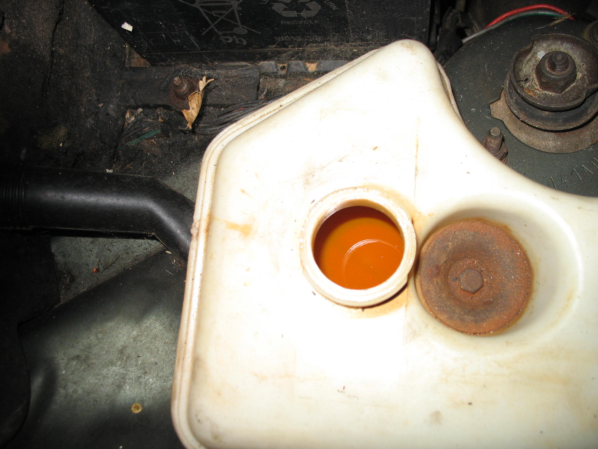
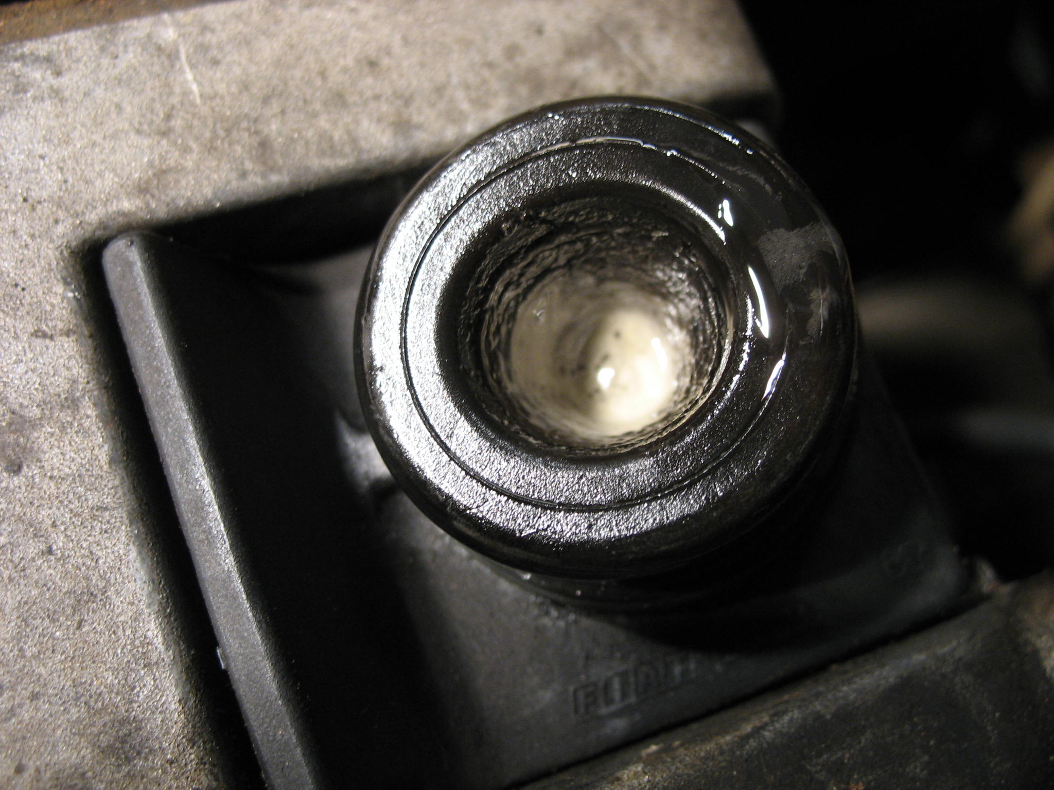
How can I confirm my head gasket theory not having coolant presure test kit???
@CLS - your not the only one - aparently it is bloody hard to buy cheepo 4x4 without blown thru head gasket.

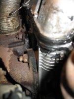
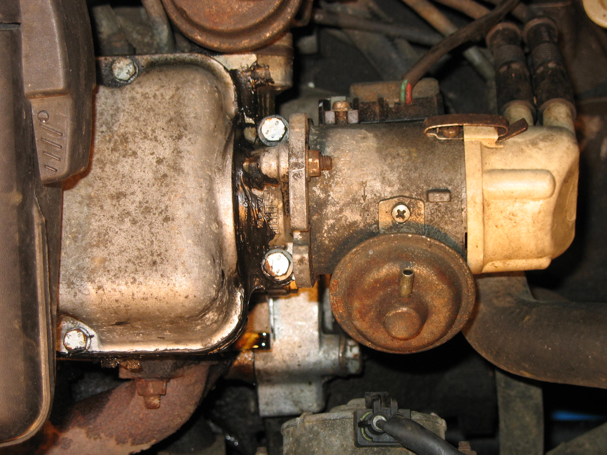
The rest of the engine bay seems to be fine,
IMG_18791.JPG


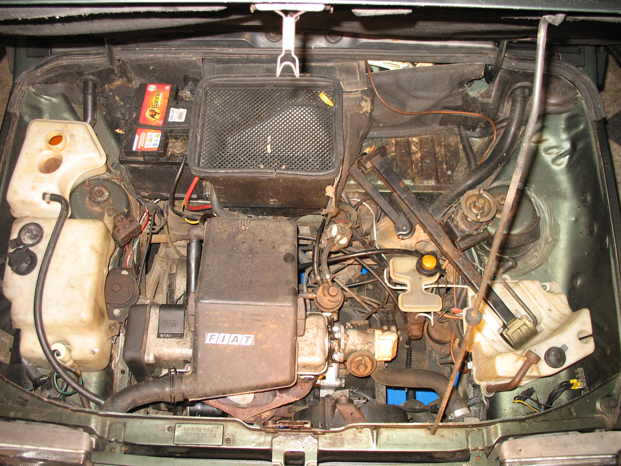
Did somebody in here mentioned a black silicone gunk as a fast repair?
IMG_1878.JPG


IMG_19241.JPG


IMG_18862.JPG


IMG_18821.JPG


IMG_19311.JPG


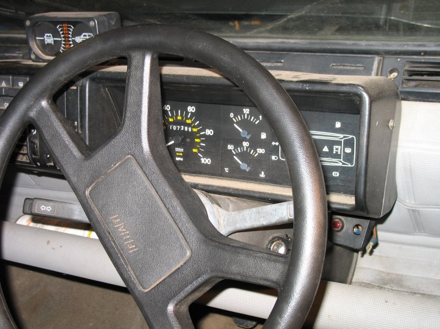
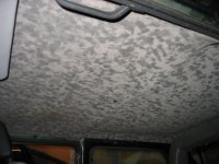
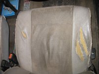
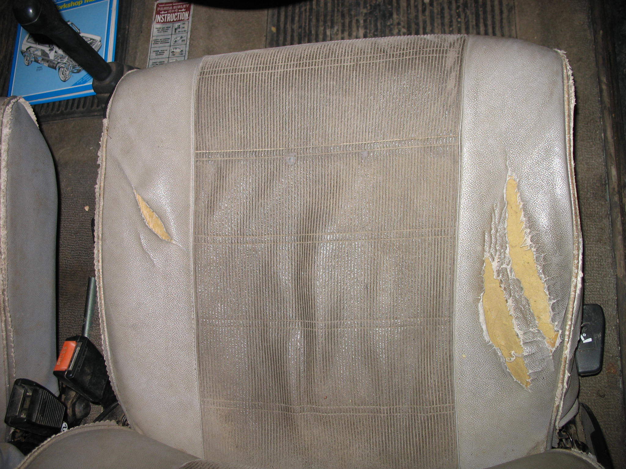
Interior as you can expect from car been used on a farm
IMG_19102.JPG


IMG_18901.JPG


IMG_1874.JPG


IMG_19373.JPG


IMG_19364.JPG


IMG_19384.JPG


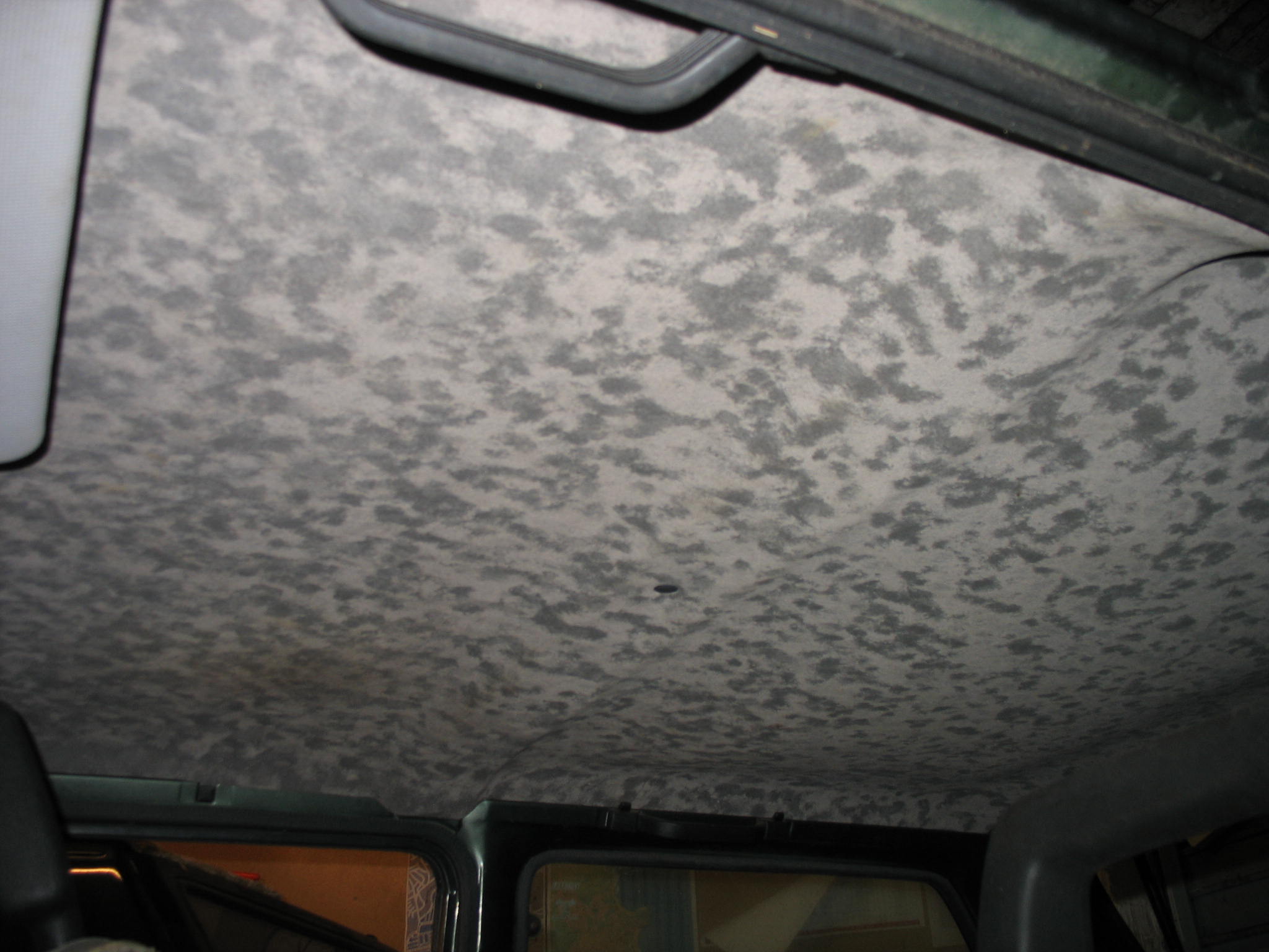
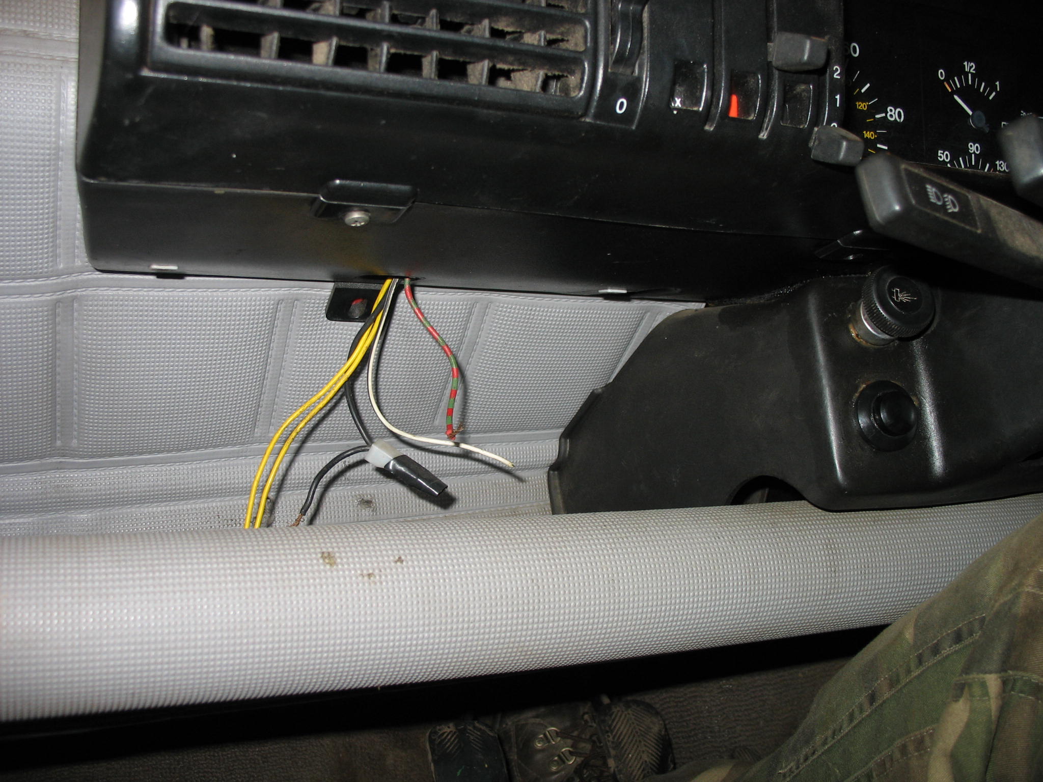
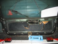
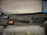
Not the geniune steering wheel and speedo, which does not make much difference to me at all. Roofrack presence evidence
IMG_18931.JPG


IMG_19081.JPG


IMG_1915.JPG


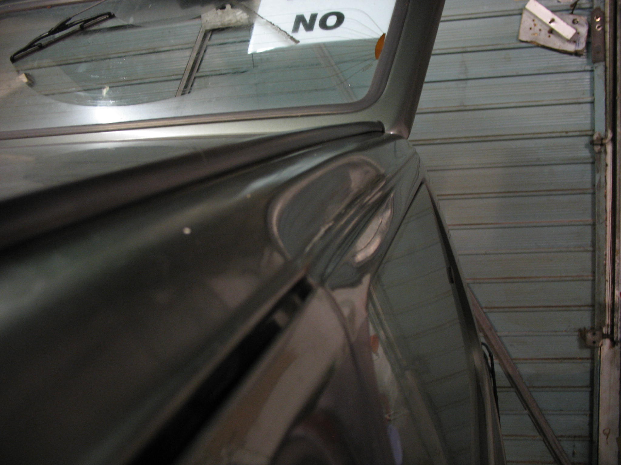
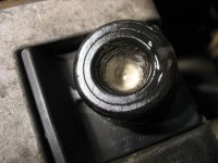
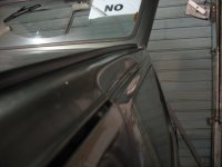
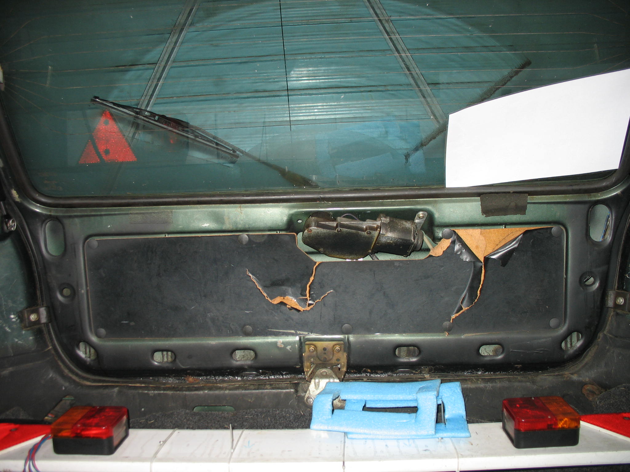
I dont want to know how this happened.
IMG_19191.JPG


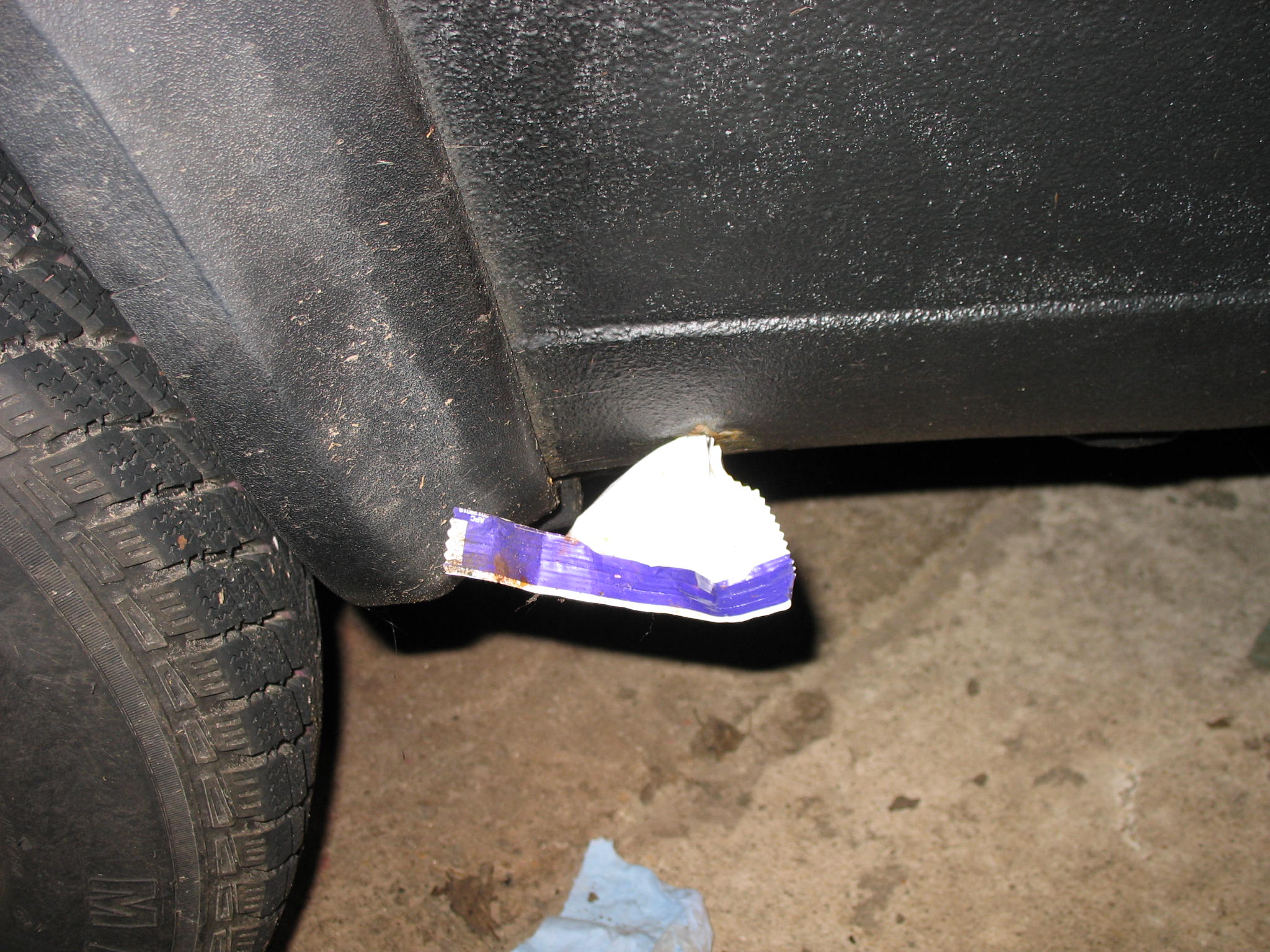
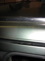
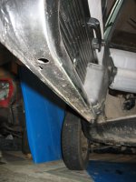
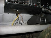
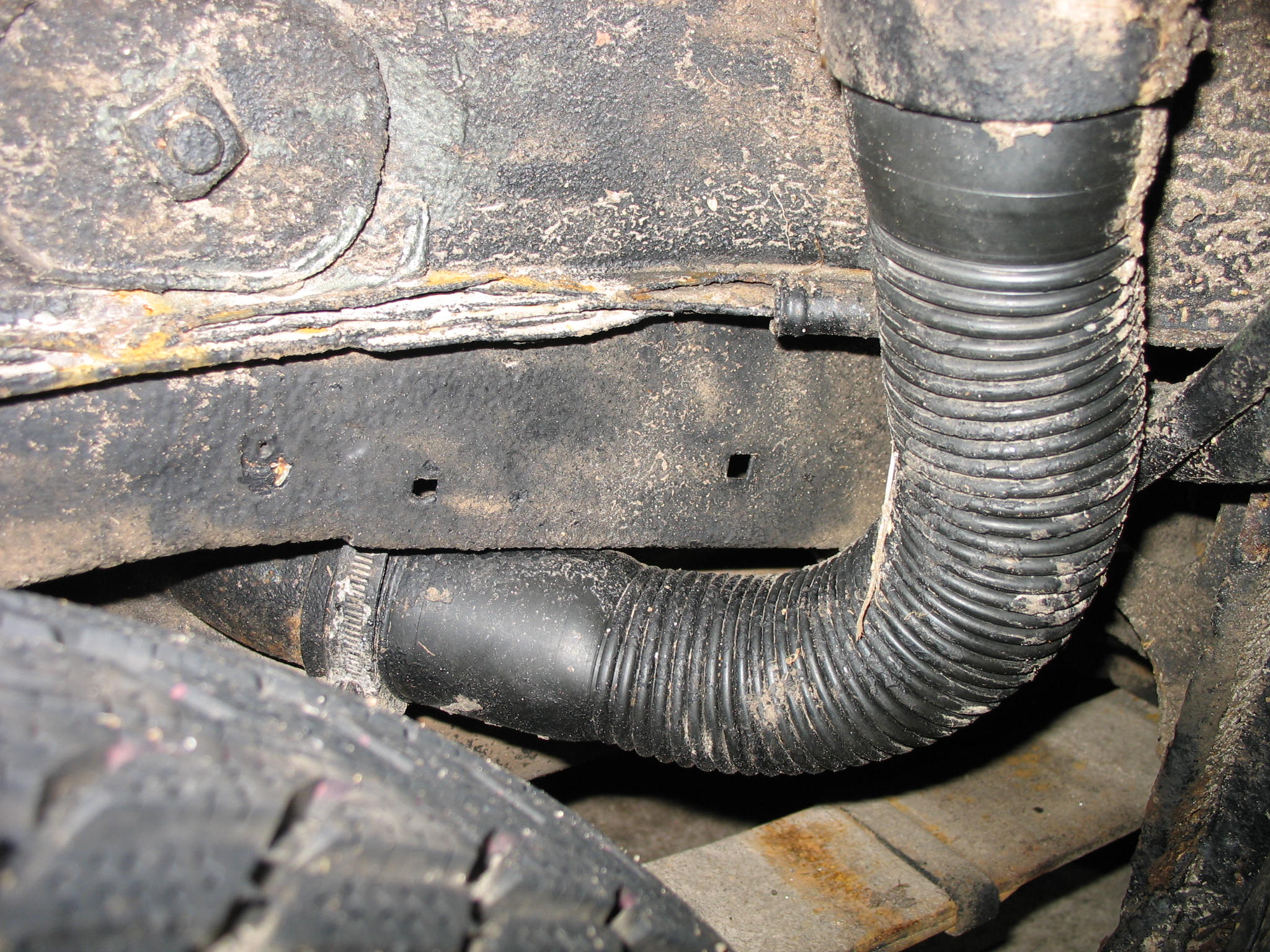
Filler pipe still untouched, what sort of DIY protections do you recon?
IMG_19202.JPG


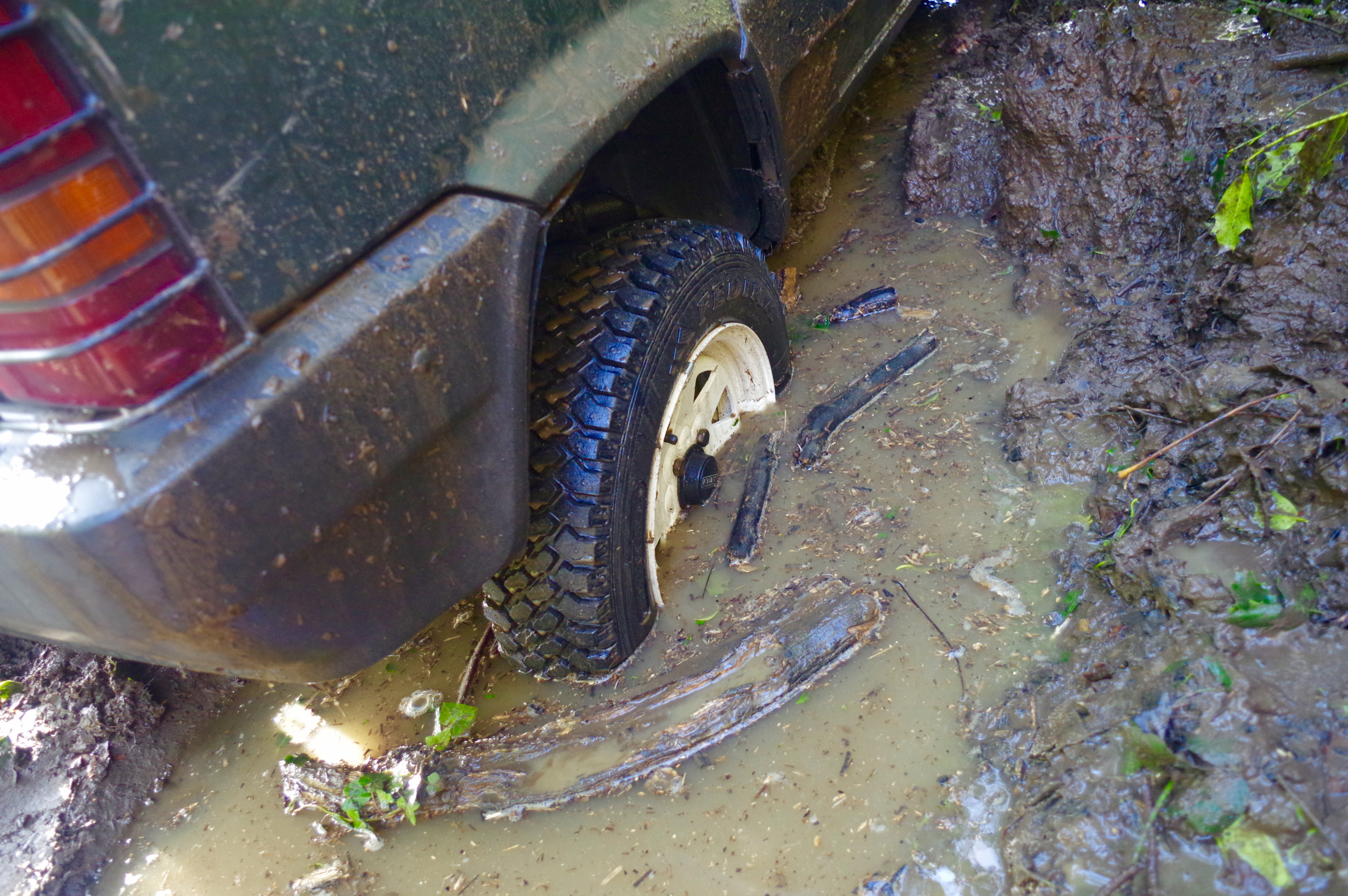
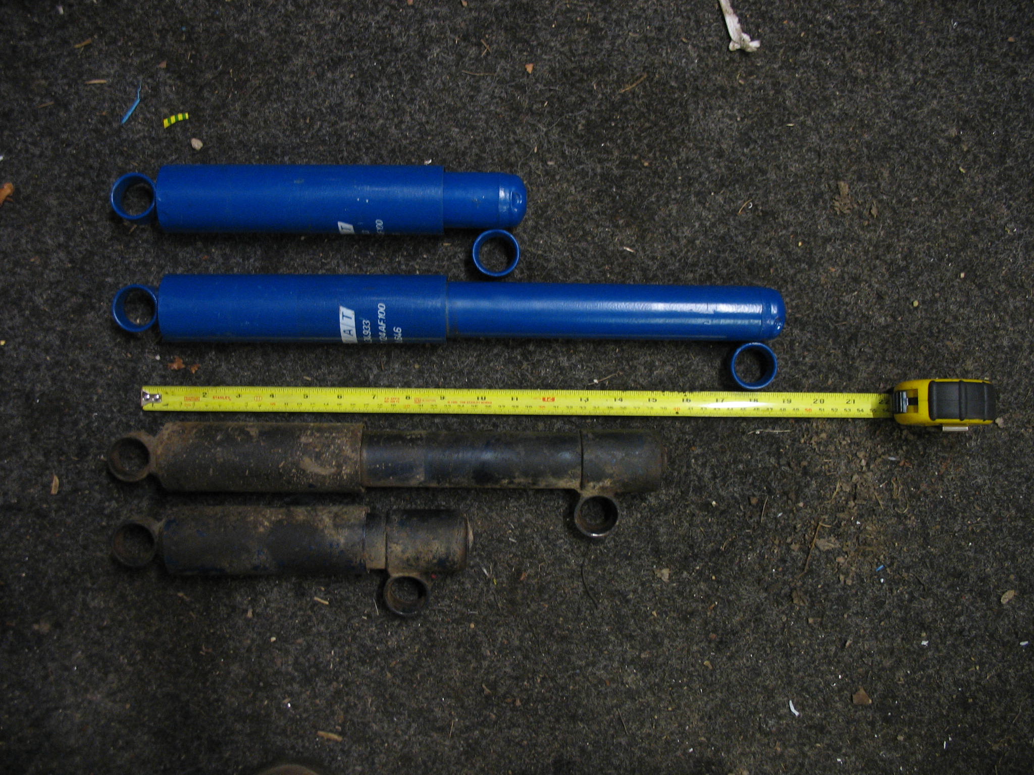
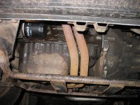
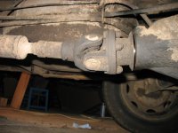
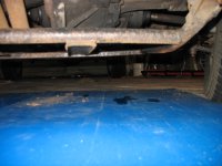
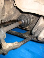
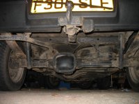
And time for the bad boy
IMG_1946.JPG


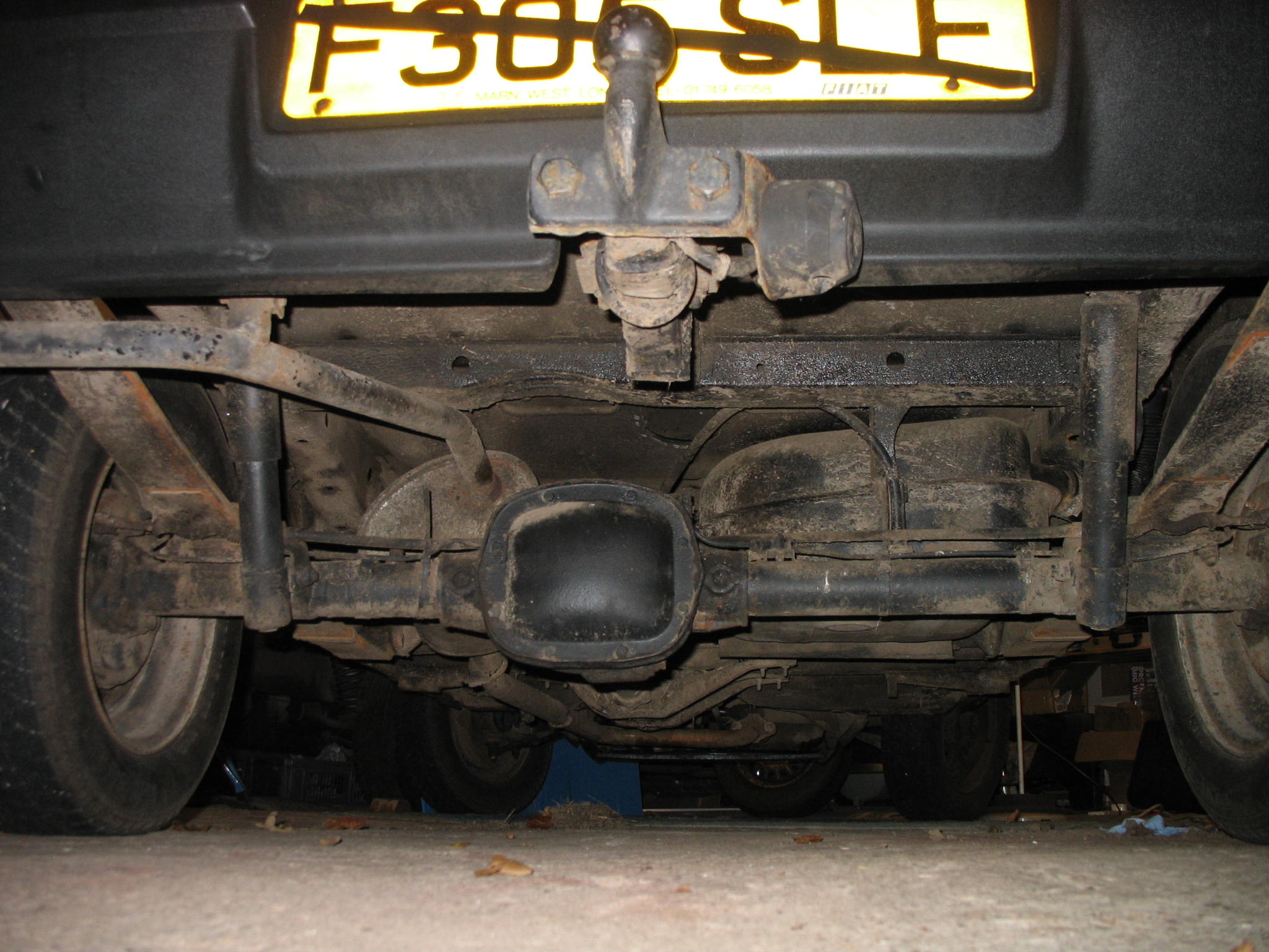
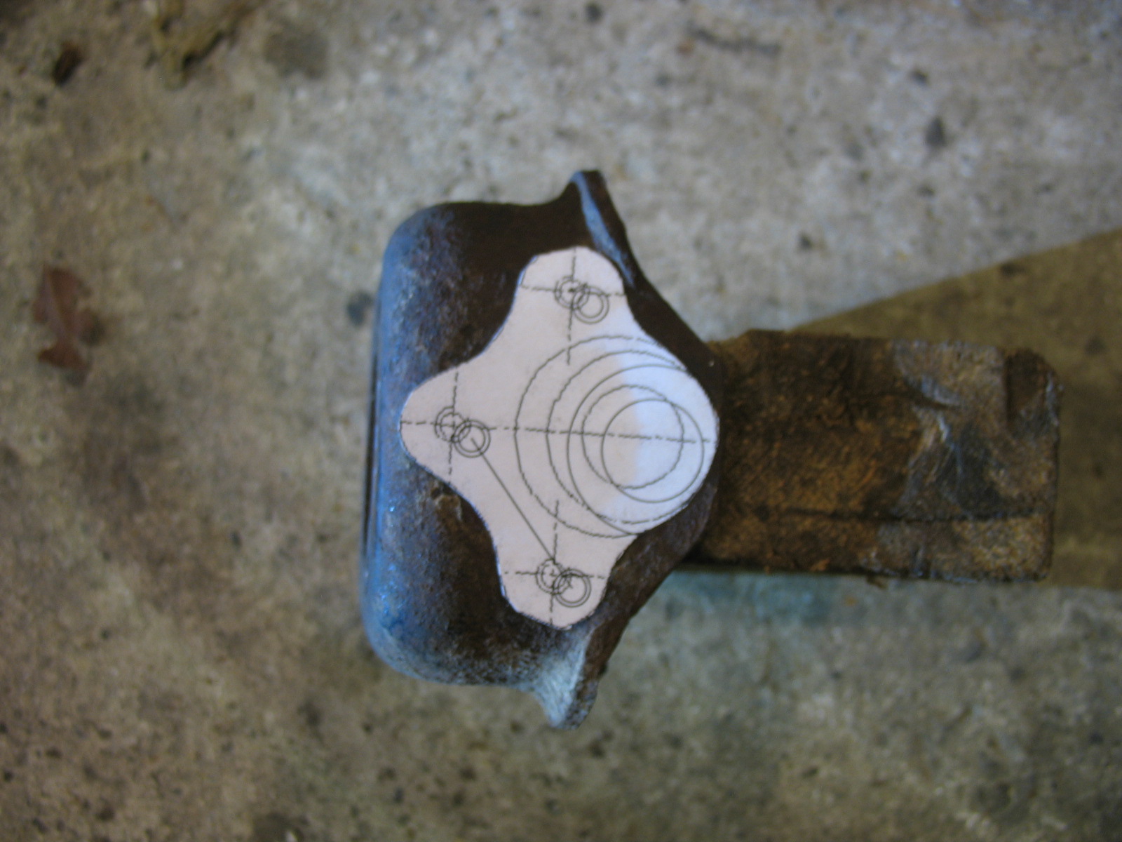
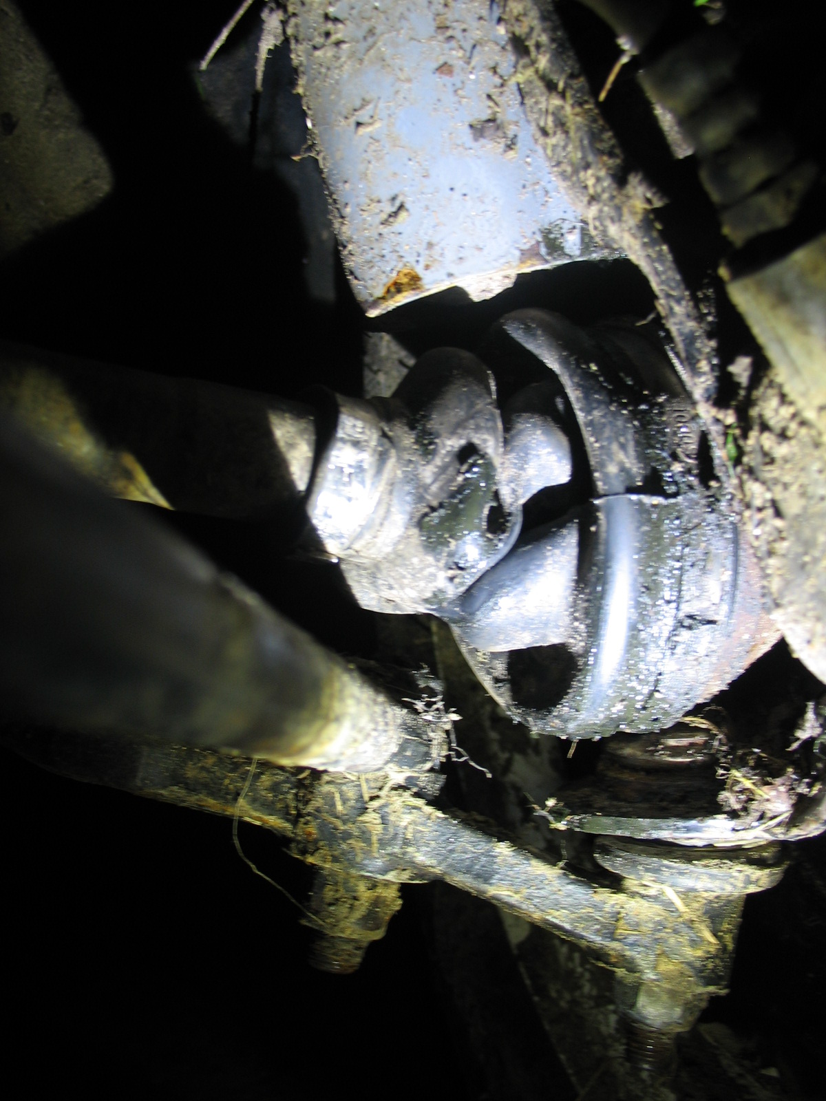
Is that gap between the propshaft and diff is normall?
IMG_19042.JPG


IMG_19022.JPG


IMG_19061.JPG


IMG_19442.JPG


IMG_19353.JPG


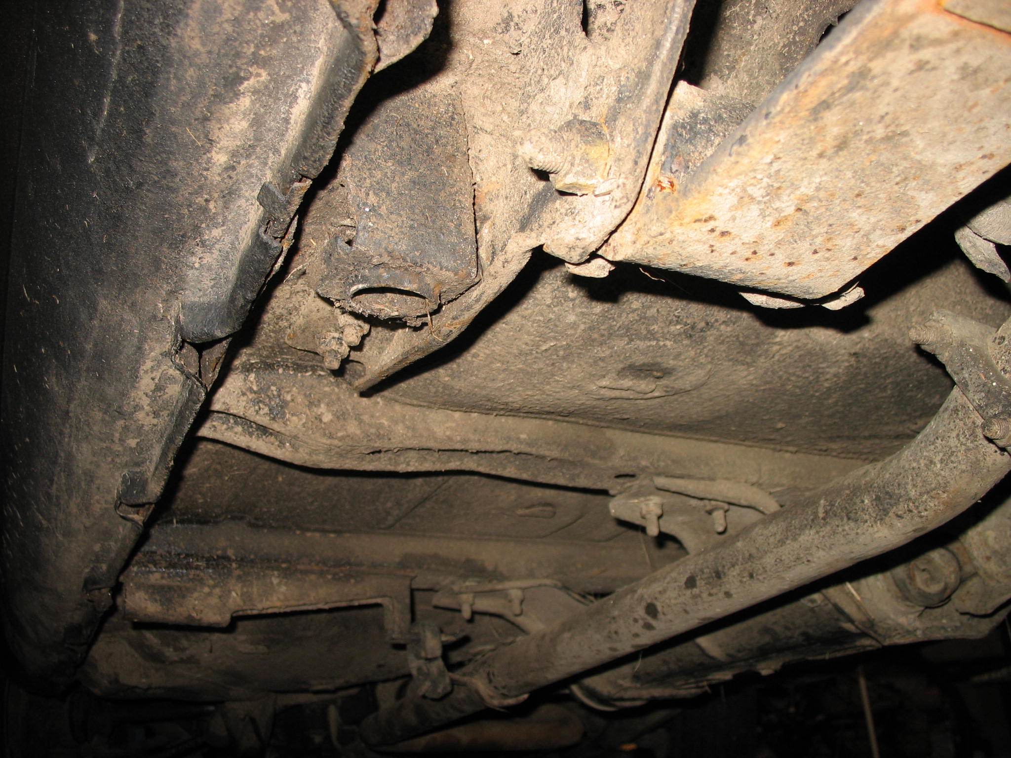
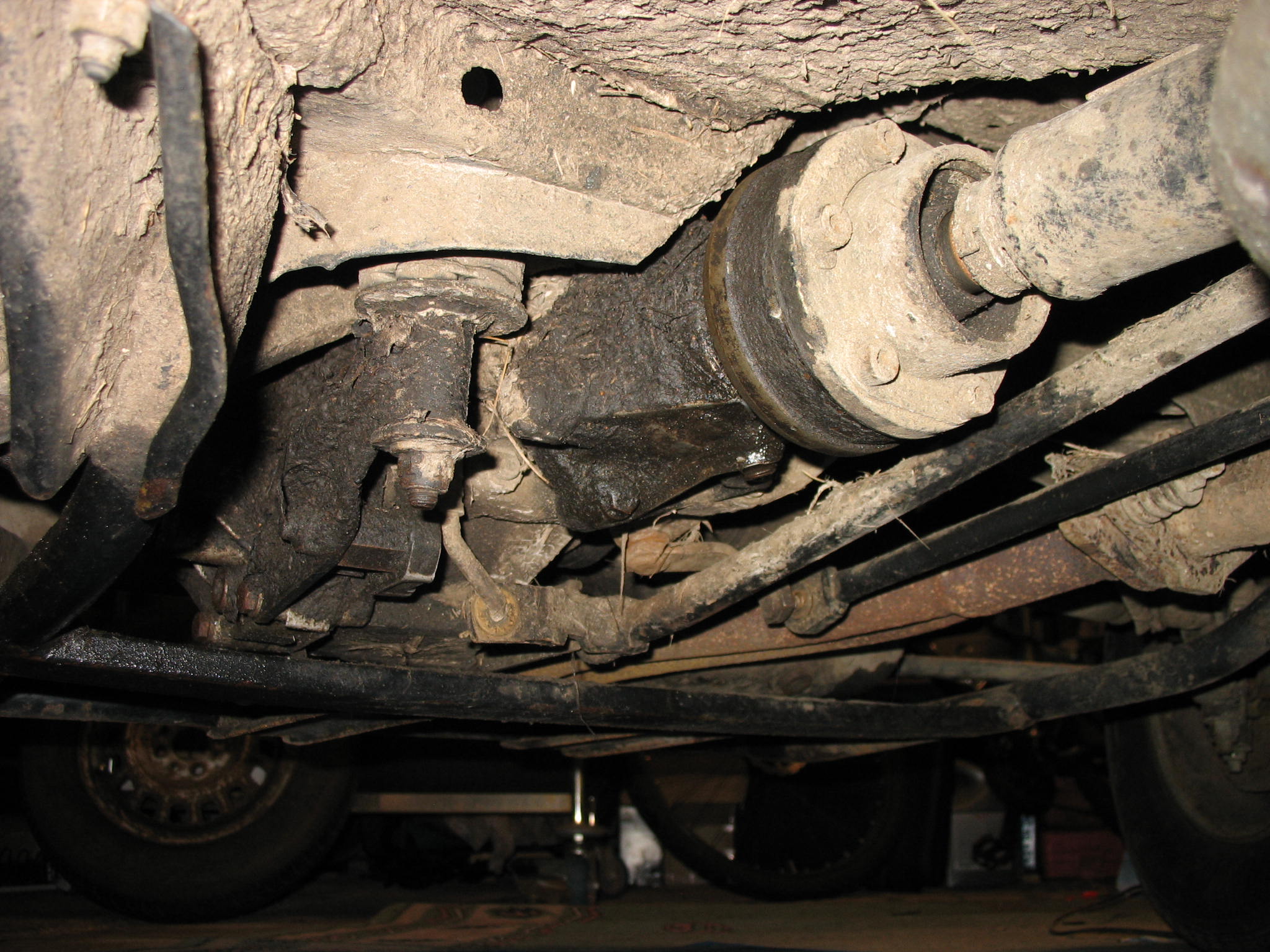
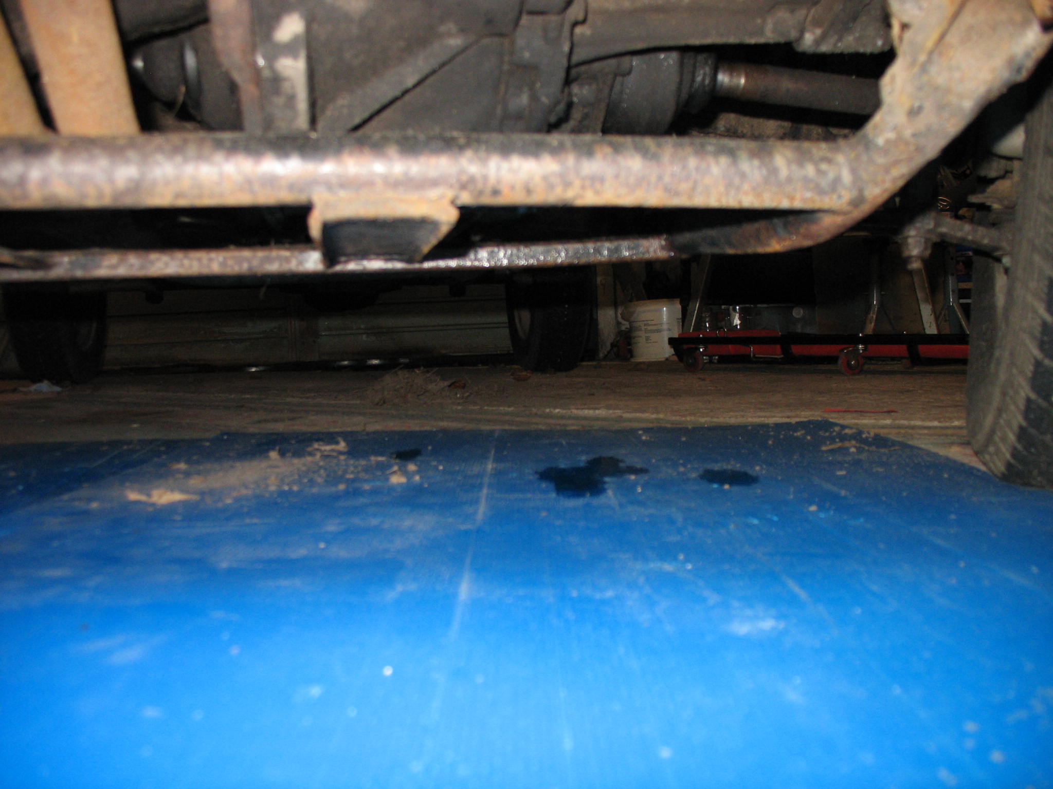
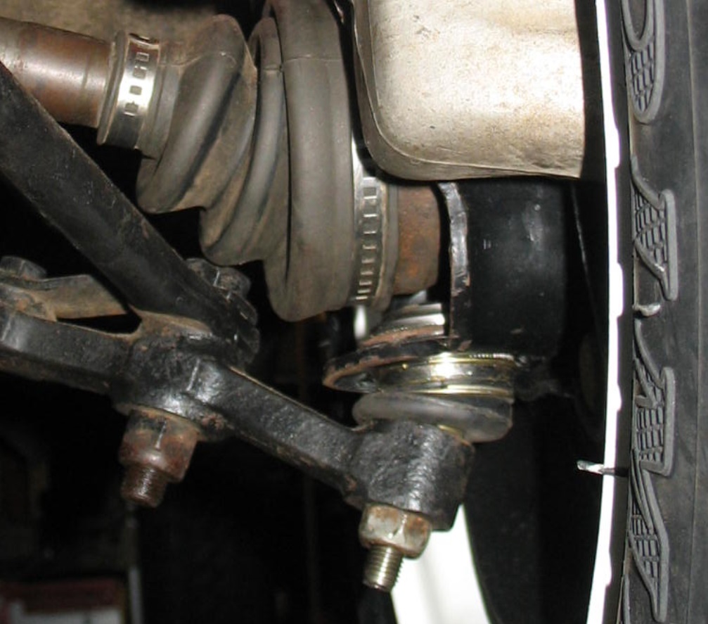
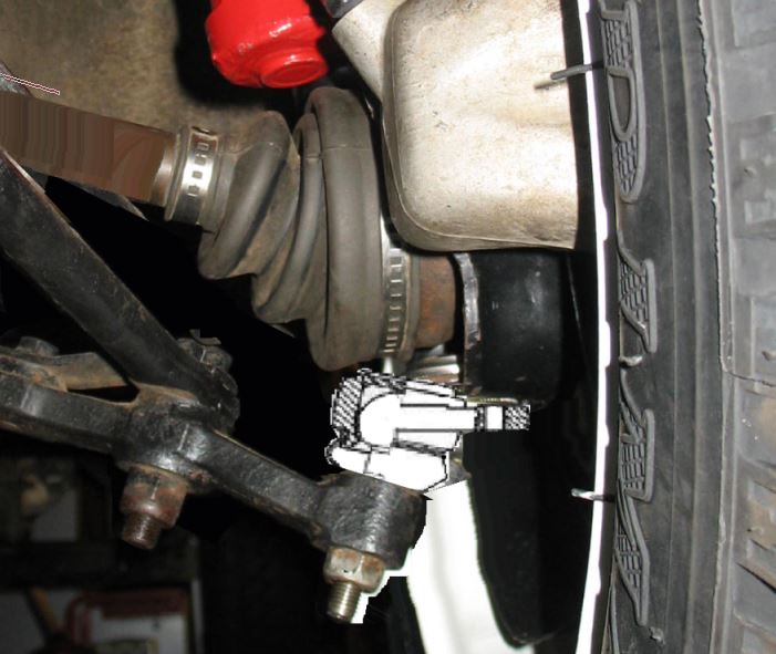
Dear FFCP section members, any comments, suggestions and observation are more than welcome, especcialy regards the 4x4 drive train i.e. leaks etc.
No reply back yet from Mr. Christian Guerriero at RialziPanda4x4, strengly enough it is first time but my last email was implying partial or full refund for partial or full kit return. I really don't want to do any black marketing, but if someone sell stuff which does not work and refuse to cooperate - in that case it is well deserved .
 
This must be Panda thing as Ula and me went out do to some laning this morning as well.

Much more been planned as i'm starting the recognition process for panday 4x4 at the coast. All went nice untll we got stuck with two wheels in massive mud filled rut, and grounded at sump guard.

I don't remember when i was that dirty, digging out with bare hands. Luckaly took bottle jack wich finally allowed us to lift front and then rear and stick few wood pieces under the wheels. Clutch was stinky at the end.

IMGP4931.jpg


IMGP4937.jpg


IMGP49461.jpg


IMGP4957.jpg


IMGP4970.jpg


IMGP4972.jpg


IMGP4973.jpg


IMGP49811.jpg


IMGP4986.jpg


IMGP4988.jpg


IMGP4998.jpg


IMGP5004.jpg


And ofcourse St@xton hill on the way back
IMGP5013.jpg


Nice ride out, but my hi-lift jack will be on board for any future laning.
 
The rubber upper part from rover 25 mount is a bit too big to fit panda upper mount, it can be probably cut to shape{ few mm from the outer diameter}. I have already cut to shape skoda favorit new rubber elements{ they were also too big few mms}, and they perfectly match rover 25 spring and panda upper "cup", so I'll use them, but also 'll try to fit to right shape the rover 25 rubbers..
ps: on the pictures there is a ritmo/strada mk1 upper mount, it is almost identical with panda item, I use them because there were two spare in the garage and I did not have second panda pair.

rover 25 spring with skoda rubber and panda/strada mk1 upper mount{ in the middle}


Last edited:
After last ride i've noticed that n/s lower ball joint need some attention.

During the suspension build the ball joint itself was replaced with new one, it did not seat tight enough from day one, photo below shows that there is gap already. After recent abuse ball joint top in nearly touching cv boot lip.
ball_joint1.jpg


I've found some PEX ball joint repair kits ( ball joint body have thread on external surface and clamp ring nut rather than jus a circlip and a grove.

Meanwihile i was looking for ball joint with simmilar spindle pitch and size but more modern body/base i.e like VAG.
My initial plan was to offset the centre of joint towards inside by 5-10mm to help with the positive camber and hubs been pulled-in when lifted susp. fitted. New balljoint would be mounted at an angle to coupe better with bigger lower arm angle.

http://www.chowjung.com/wp-content/uploads/2015/04/3B-3071-2-500x435.jpg

After a while i have realized that top mount, cv ball bearing races and lower ball joint are should be in-line for steering purposes.

The question is how far can the lower joint be offset to allow the cv joint operation without any issues?
 
Last edited:
I use only ball joints with thread on external surface, those with circlip and a grove will always get some play. Fiat designed the front "Control Arm"{part no1, pillar on the first pct. number 5976943} as a whole unit, pressed steel with ball jont, it is one element with one part no. in eper, and it is designed to be replaced as a whole unit.But the ball joint itself is the same as in fiat uno or some other fiats therefore most people including me replace only joint. But when you press in and out few times a ball jont from the control arm the "hole" fot the joint gets bigger and does not hold the joint in place firmly.

I also make few "dots" with mig to ensure that the balljoint will stay where it shoud be.Small weld dots are easy to grind off during next joint replacement n the future.


ps: consider straightening the swinging arms, it needs to be heated{yellow hot} and hammered, or better pressed to make the end straight, it will change/improve the angle of ball joint operation

here a picture of straightened arms:

 
Last edited:
No reply back yet from RialziPanda4x4, strengly enough it is first time but my last email was implying partial or full refund for partial or full kit return. .

Contact has been made, faulty email system of course.
Replacement parts proposed to me ,not happy yet as R25 spring serves me well no need for others. Getting the detailsfrom them guys is a PITA and they don't use punctuation marks which makes it even harder when using google translate. :bang:
 
New shocks has been sourced for the rear, masive difference when compared to 4wd std shocks. comparing to 2wd shocks those are 450/270, 180 stroke.

Standard 4wd rear ride hight between eyelets is 300mm, 15mm lift from shackle and 40mm lift from axle spacer give you 355mm new ride high.

2wd shock is 420/253, 168 stroke, so 355mm will give you 65mm downward travel and 102mm upward travel.

new shocks is 450/270, 180mm stroke, 95mm upward travel and 85mm downward so i'm looking forward to a bit more max articulation at the back. Time will tell as they came from slightly bigger car and much higher pull-out force is required.

IMG_34772.JPG


Mazda B2 series upper ball joint template been printed out for some more checks, still not 100% sure but as i've found out I need to change them sunner than later as cv boot retainting band lock bit did catched loose ball joint body casing boot to twist by almost 1/2 turn, boot is split now.
IMG_34802.JPG


I know exactly when that happend, when we wer stuck in that lane with no grip at front left and rear right. Front was on maximum articulation and on full speed.

I was aking myself, would my brake pipe locking hydraulic system worked in this situation.
Winch is scheduled for May.

IMG_3484.JPG


Meanwhile i'll be getting pair off ball joint repair kits from Germany. If someone is interested please let me know, £12/pair + UK postage.
 
Last edited:
Renault 4, 5,6 lower and upper ball joints have same spindle size, base isn't at an angle but that can be overcome with some spacers. NOS on ebay is cheap enough to give a go and trial one pair.
 
Did anybody been considering converting the freelander cage type roof rails to fit to panda? I'm trying to visualize that as it might be good looking.

Both rear pillars would have to be reshaped to more panda tail gate angle, i don't thing front points would reach up to A pillar, so extend them further with bits removed fron the rears or cut and get the front bolted down near B pillars.

panda_freelander_cage.JPG
 
as far as I found:

p4x4 1.0 fire:

525mm short 815mm long

uno 1.0 1.1 fire

555mm short 870mm long

these above probably include the lenght of the shafts plus CV joints.{ spidan lauber etc sells whole "repair kit" with boots cv joint and shaft, not bare shaft} I'll try to find more in this topic.

ps long is probably 634mm, uno long one?
 
Last edited:
I think it is less than 30mm on the picture, have found, that fiat 127 sport had 535mm short drive shaft= 10mm longer than panda 4x4.{ probably every f127 with 1050 ccm/1300 engine} f127 903ccm had 547mm short one.
 
Last edited:
I've measured one full short shaft + cv from my selection and it was 535mm, same as some listed for pandas. So the uno 555mm one will be the right one, and actually 20mm is perfect as bottom ball joint can be shifted by 20mm towards the gearbox.
More details to follow, if few words as you are lifting the car distance between front wheels is reduced and the NS shaft angle is at pretty step angle. By having longer shaft and hub further away the shaft angle will be smaller.
 
Last edited:
To get better idea of geometry changes in the front suspension I've drawn simple model ( wish I had 3D package at work).


Drawing shows the principle of the design.
- strut, drive shaft, lower arm, hub carrier, lower arm mounting point and driveshaft at diff.


I don't have correct components dimensions for now so I've used units instead of cm and kept proportion more less as they are.


You can see that after extending the strut by 10 units and adjusting the camber to initial value the bottom ball joint relocate towards gearbox almost by half of the lift value, drive shaft sits 2.8 units further inside gearbox and shaft angle has change by 7 degrees.


So, what its all about? I want to investigate getting over that problem with extended lower arm or relocated ball joint and longer shaft if necessary.
 

Attachments

  • lift geometry Model (1).pdf
    9.3 KB · Views: 62
Back
Top