

You are using an out of date browser. It may not display this or other websites correctly.
You should upgrade or use an alternative browser.
You should upgrade or use an alternative browser.
Technical Multipla JTD 1.9 Clutch Replacement (in progress...)
- Thread starter MarkX
- Start date
Currently reading:
Technical Multipla JTD 1.9 Clutch Replacement (in progress...)
My LUK DMF hasn't given any trouble since it was fitted (along with an LUK clutch).
That's good to know.
The thing to look at when you get it all apart is the condition of the 'fingers' in the centre of the clutch. Mine & several others had quite a deep groove worn into them by the clutch release bearing, even after a relatively short period of time
I'm very curious to see for myself the damage on my car.
As Portland Bill says, it could be the result of the release bearing not being held concentric to the clutch, in which case the clutch fork arm and its bearings may be the culprit
My clutch fork arm was well wobbly/loose after I removed the clutch slave cylinder. Hoping that new fork bushes/bearings (they're made of plastic by the way) will tighten things up/improve things. I did enquire at Fiat about replacing the fork shaft as well as the bearings, but Fiat said it's not a separate part, you have to buy the whole clutch fork kit. Tempted to fork out (sorry I couldn't resist it) £80 for the whole clutch fork kit. Lot of work to take the bellhousing off again later just to do the clutch fork.
Incidently, the surface of the fingers on my new clutch are quite rough. I am assuming they'll wear smooth over time.
Incidently, the surface of the fingers on my new clutch are quite rough. I am assuming they'll wear smooth over time.
That should be: "the surface of the fingers on my new clutch is quite rough" !
Hello Folks,
I had a long (12:00 to 21:00), but productive day Today. Rain had been forecast so I wasn't expecting to get much done, but apart from a brief shower, it was fine, sunny and warm for most of the day.
Progress:
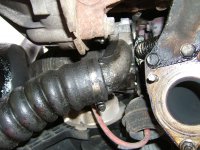
- Removed intercooler hoses
- Removed air hose
- Detached NS track rod end
- Constructed bellhousing lifting/shifting device
Removed intercooler hoses
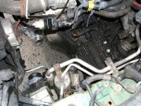
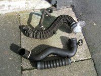
I first completely removed the two intercooler hoses. The bottom hose was covered in black gunk (See pic). A hose clip to remove at the ends of each hose (See pic). 10 minutes work.
Removed air hose
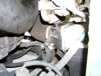
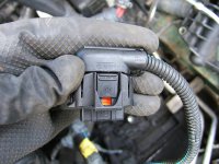
I then removed the air hose, after disconnecting the MAF sensor connector. I scratched my head trying to work out how to disconnect the MAF connector from the hose. Solution: Push in a latch on the back side of the connector (See pic). One jubilee clip to disconnect the large hose from the engine, one smaller hose off the large hose to disconnect at the top of the engine (See pic), and remove the hose from the engine bay.
If you are wondering whether it's worthwhile removing these 3 hoses (See pic), I would say just do it. It's a doddle, only a few minutes work, and improves access and clearance for bellhousing removal (See pic).
Tip: I bought 50 small sandwich bags and some rubber bands to protect inlets, outlets etc (See pic), and to bag up small, removed parts (bags then labelled with a marker pen).
Detached NS track rod end (See pic)
In a previous post, I described a mistake I made trying to disconnect the track rod end ball joint from the NS hub. Tried again Today using the technique described in the Youtube video I posted earlier, where you lever the track rod end ball joint/pin against the hub. Didn't work because I couldn't find much to lever against. I resorted to sawing through the pin just above the stuck nut. (I put a new, hardened steel blade in my junior hacksaw. It only managed to saw though half the pin. When I checked the blade all the teeth had disappeared! So I completed the job with my 10 year old hacksaw blade. "Eeeh lad they don't make them hacksaw blades like they did in my day...".
Once I'd released the track rod end from the hub, I marked the position of the track rod end on the track rod with a cable tie and marker pen (See pic), then loosened the track rod end lock nut, removed the track rod end and lock nut, and cleaned up the track rod screw thread and lock nut with a wire brush attachment on my portable drill. To clean things up further I spun the lock nut back and forth on the screw thread with some WD40 (See pic). Reassembled everything to put the road wheel back on later. OS track rod end still to do.
Constructed bellhousing lifting/shifting device
I spent the rest of the day constructing my lifting/shifting device which involved some school woodwork and metalwork. There is still a little work to do tomorrow to complete the design and construction. What I can tell you is that the device will provide movement in all 3 dimensions: up/down, side-to-side (OS to NS), and front to back. I have to be honest and revise the price of the device: £3 + £5 + £2-50 + £3 ish = £13-50, plus a few bits and pieces scavenged from around the house. Let's say £15. A bit cheaper than Notes for Novices Sealey Engine Support Beam (about £70 on Ebay Today), and hopefully just as functional. I will give full details later, if it works...
Tip: If you are using any sort of lifting/shifting device in the engine bay above the bellhousing, you may find it helpful to unbolt (Note: unbolt only) the coolant bottle (2 x 8mm nuts), brake/clutch fluid reservoir (2 x 10mm nuts), and big black fuse box in the engine bay above the NS wheelarch (just slide it up off the bracket it's attached to), and move all three out of the way of your lifting device. I did. A few minutes work.
Very happy with progress Today.
Mark
I had a long (12:00 to 21:00), but productive day Today. Rain had been forecast so I wasn't expecting to get much done, but apart from a brief shower, it was fine, sunny and warm for most of the day.
Progress:
- Removed intercooler hoses
- Removed air hose
- Detached NS track rod end
- Constructed bellhousing lifting/shifting device
Removed intercooler hoses
I first completely removed the two intercooler hoses. The bottom hose was covered in black gunk (See pic). A hose clip to remove at the ends of each hose (See pic). 10 minutes work.
Removed air hose
I then removed the air hose, after disconnecting the MAF sensor connector. I scratched my head trying to work out how to disconnect the MAF connector from the hose. Solution: Push in a latch on the back side of the connector (See pic). One jubilee clip to disconnect the large hose from the engine, one smaller hose off the large hose to disconnect at the top of the engine (See pic), and remove the hose from the engine bay.
If you are wondering whether it's worthwhile removing these 3 hoses (See pic), I would say just do it. It's a doddle, only a few minutes work, and improves access and clearance for bellhousing removal (See pic).
Tip: I bought 50 small sandwich bags and some rubber bands to protect inlets, outlets etc (See pic), and to bag up small, removed parts (bags then labelled with a marker pen).
Detached NS track rod end (See pic)
In a previous post, I described a mistake I made trying to disconnect the track rod end ball joint from the NS hub. Tried again Today using the technique described in the Youtube video I posted earlier, where you lever the track rod end ball joint/pin against the hub. Didn't work because I couldn't find much to lever against. I resorted to sawing through the pin just above the stuck nut. (I put a new, hardened steel blade in my junior hacksaw. It only managed to saw though half the pin. When I checked the blade all the teeth had disappeared! So I completed the job with my 10 year old hacksaw blade. "Eeeh lad they don't make them hacksaw blades like they did in my day...".
Once I'd released the track rod end from the hub, I marked the position of the track rod end on the track rod with a cable tie and marker pen (See pic), then loosened the track rod end lock nut, removed the track rod end and lock nut, and cleaned up the track rod screw thread and lock nut with a wire brush attachment on my portable drill. To clean things up further I spun the lock nut back and forth on the screw thread with some WD40 (See pic). Reassembled everything to put the road wheel back on later. OS track rod end still to do.
Constructed bellhousing lifting/shifting device
I spent the rest of the day constructing my lifting/shifting device which involved some school woodwork and metalwork. There is still a little work to do tomorrow to complete the design and construction. What I can tell you is that the device will provide movement in all 3 dimensions: up/down, side-to-side (OS to NS), and front to back. I have to be honest and revise the price of the device: £3 + £5 + £2-50 + £3 ish = £13-50, plus a few bits and pieces scavenged from around the house. Let's say £15. A bit cheaper than Notes for Novices Sealey Engine Support Beam (about £70 on Ebay Today), and hopefully just as functional. I will give full details later, if it works...
Tip: If you are using any sort of lifting/shifting device in the engine bay above the bellhousing, you may find it helpful to unbolt (Note: unbolt only) the coolant bottle (2 x 8mm nuts), brake/clutch fluid reservoir (2 x 10mm nuts), and big black fuse box in the engine bay above the NS wheelarch (just slide it up off the bracket it's attached to), and move all three out of the way of your lifting device. I did. A few minutes work.
Very happy with progress Today.
Mark
Attachments
-
 DSCF1173 1.JPG216.2 KB · Views: 39
 -
 DSCF1175.JPG339.6 KB · Views: 37
 -
 DSCF1172.JPG220.6 KB · Views: 38
 -
 MAF.JPG228.6 KB · Views: 51
 -
 DSCF1183.JPG259.6 KB · Views: 36
 -
 TRE Marked.JPG168.3 KB · Views: 55
 -
 Track Rod End NS.JPG199.5 KB · Views: 43
 -
 DSCF1186 2.JPG348.8 KB · Views: 41
 -
 Clearance after hose removal.JPG355.4 KB · Views: 51
 -
 Air hose & Intercooler Hoses.JPG468.3 KB · Views: 41
 -
 Track Rod Cleaned Up.JPG180.8 KB · Views: 49
Last edited:
Today's update...
Not much to report. Ran around chasing parts for my DIY bellhousing hoist.
The second Fiat jack has arrived at last. Just been to pick it up from the parcel shop. Well wrapped and in very good condition. Bargain at £22 inc P&P vs £58? at Fiat. The last obstacle is out of the way, the weather looks OK for the next 2 days, and I think I have everything I need for the job, so I can get cracking Tomorrow. I hope to have the car safely back on it's wheels by close of play on Wednesday.
As previously warned, I reserve the option to abandon the job if I decide it isn't safe for me to do, or it's beyond my capabilities, and to tow the car to a garage or scrapyard. Hopefully neither of those two options will apply. We shall see...
Mark
- Joined
- Feb 1, 2008
- Messages
- 755
- Points
- 175
I have never seen so much prep work go into a job before...good luck!
Mine was pretty straight forward but I ran into problems with the gearbox mount...so I say be careful there as the captive nut comes loose...
Mine was pretty straight forward but I ran into problems with the gearbox mount...so I say be careful there as the captive nut comes loose...
Question for anyone who's already done a Multipla clutch/removed the bellhousing...
If I need to drop the front subframe, is it as simple as Notes for Novices Section 32 Lower front subframe makes it sound: remove the 3 bolts on NS of the subframe and undo all the bolts on the OS about 25mm? (this apparently drops the subframe on NS about 50mm)
Anyone done this? Does it work?
Mark
If I need to drop the front subframe, is it as simple as Notes for Novices Section 32 Lower front subframe makes it sound: remove the 3 bolts on NS of the subframe and undo all the bolts on the OS about 25mm? (this apparently drops the subframe on NS about 50mm)
Anyone done this? Does it work?
Mark
Progress Today:
Completed lifting/shifting device: 2 problems to solve: 1) How to grab hold of the bellhousing, and 2) The hoist uses a vertical rod to provide the lifting/lowering motion, but there is no hook or eye at the bottom end of the rod to attach the hoist to whatever attaches to the bellhousing.
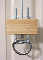
Problem 1: How to grab hold of the bellhousing: First idea was to screw 2 short eye bolts into the clutch slave cylinder holes (M8 thread), then a large 'D' shackle through the eye bolts (see shackle in pic below). Did this. Looks good and solid, but where's the centre of gravity of the bellhousing? Suspect it's not where the slave cylinder sits.
Second idea was to buy 1m of welded 3cm link chain (£3-30). This just fits around the bellhousing at the point where the gearbox meets the clutch housing. Joined the 2 ends of the chain together with a large 11cm carabiner (yes, I have one). Sorted.
Problem 2: How to connect the vertical M8 lowering/lifting rod to the chain: Well I scratched my head for a lonnnnnngggg time. You see I have only very basic metalworking tools: a junior hacksaw, and a portable drill which on a good day will drill through a block of mature cheddar. However, I do have quite a few woodworking tools.
First thought was to attach an M8 eye bolt to the end of the rod with some nuts, maybe superglue everything together. But this arrangement felt intuitively weak/naff. Well to cut a long story short, I came up with the device/block below (See pic). Some of it's features: a) It solves the problem of how to attach the vertical rod to the bellhousing grab/chain, b) Under load the wooden block is under compression so hopefully it should be quite strong, c) It swivels, d) It's as small as I could make it, to allow maximum freedom of movement in the confined operating space, e) Once the lowering/lifting rod is at it's lowest/highest point, the eye bolts in the block can be lowered/raised a further 4cm, or independently to lower/lift at an angle, f) It's relatively cheap to make:
2 x 15cm M8 eye bolts (£2-50)
Wings nuts, nuts and washers (£2 Pick & Mix bag of bits from Wilkos)
Piece of wood 4 x 6 x 12.5cm (£pennies)
'D' shackle (£0 - already had one, sorry )
Total cost (to me): £3 ish
Finished and assembled the rest of the hoist in/over the engine bay. Looks OK but how will it handle a 37kg bellhousing?
Mark
Completed lifting/shifting device: 2 problems to solve: 1) How to grab hold of the bellhousing, and 2) The hoist uses a vertical rod to provide the lifting/lowering motion, but there is no hook or eye at the bottom end of the rod to attach the hoist to whatever attaches to the bellhousing.
Problem 1: How to grab hold of the bellhousing: First idea was to screw 2 short eye bolts into the clutch slave cylinder holes (M8 thread), then a large 'D' shackle through the eye bolts (see shackle in pic below). Did this. Looks good and solid, but where's the centre of gravity of the bellhousing? Suspect it's not where the slave cylinder sits.
Second idea was to buy 1m of welded 3cm link chain (£3-30). This just fits around the bellhousing at the point where the gearbox meets the clutch housing. Joined the 2 ends of the chain together with a large 11cm carabiner (yes, I have one). Sorted.
Problem 2: How to connect the vertical M8 lowering/lifting rod to the chain: Well I scratched my head for a lonnnnnngggg time. You see I have only very basic metalworking tools: a junior hacksaw, and a portable drill which on a good day will drill through a block of mature cheddar. However, I do have quite a few woodworking tools.
First thought was to attach an M8 eye bolt to the end of the rod with some nuts, maybe superglue everything together. But this arrangement felt intuitively weak/naff. Well to cut a long story short, I came up with the device/block below (See pic). Some of it's features: a) It solves the problem of how to attach the vertical rod to the bellhousing grab/chain, b) Under load the wooden block is under compression so hopefully it should be quite strong, c) It swivels, d) It's as small as I could make it, to allow maximum freedom of movement in the confined operating space, e) Once the lowering/lifting rod is at it's lowest/highest point, the eye bolts in the block can be lowered/raised a further 4cm, or independently to lower/lift at an angle, f) It's relatively cheap to make:
2 x 15cm M8 eye bolts (£2-50)
Wings nuts, nuts and washers (£2 Pick & Mix bag of bits from Wilkos)
Piece of wood 4 x 6 x 12.5cm (£pennies)
'D' shackle (£0 - already had one, sorry )
Total cost (to me): £3 ish
Finished and assembled the rest of the hoist in/over the engine bay. Looks OK but how will it handle a 37kg bellhousing?
Mark
Attachments
Last edited:
Hello Folks,
The saga continues...
Jacking up
Couldn't start till late on Today, so plan was just to get car safely raised with the scaffolding boards, chocks and 2 Fiat jacks. Don't worry, I intend to install axle stands, wheels, etc. under the car as well for safety. I nailed and screwed the boards to the chocks to make things more secure.
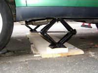
I found out something interesting when jacking up the car with the Fiat jacks. Note that the base of each jack is now at the same level, sitting on a horizontal platform. Initially I placed the jacks under the front jacking points as prescribed, with the points of the scissor facing OS and NS across the car. I was careful to raise both sides of the car gradually, a little at a time. When I got so far, because the base and top of the jack is articulated, the OS jack I was raising began to tilt sideways on it's base towards the NS, and as the jack tilted, the car began to shift to the NS. Fortunately, because both jacks were at a similar height it didn't take much manual force to stop the car sliding while I quickly lowered the OS jack. Wow, I thought, it's not safe to use these jacks in the standard way under the jacking points.
So, I lowered the car back onto it's wheels, turned the jacks through 90 degrees (parallel to the sides of the car) so that the points of the scissor now faced the front and rear of the car, and placed each jack's top platform (very carefully) under the longitudinal beams at the sills about 4cm from the front jacking points. To test the stability of this arrangement I tried shoving the car from side-to-side and front-to-back. I also took the advice of a forum-er in a previous post and bounced up and down a bit inside the car. The car wobbled a bit as you'd expect, but stayed up (See pics below).
Starter motor, top rear bolt
Because I'm a masochist I decided to have a go at the starter motor top rear (13mm) bolt. The bolt appears to be way over-torqued, so a short stubby 13mm spanner, as some people have suggested, didn't budge the bolt head, or a normal length spanner, because there's no clearance at the back of the engine to move the spanner.
I couldn't reach the bolt head, from under the car, with a 1/2" wrench and 4.5" extension as access is tight. What would've worked is a 3/8" drive socket and extension (extension length around 6" (15cm). Maybe get one tomoz.
Instead I deviced my own extension from a round-headed, 6" (15cm) bolt, with the round end of the bolt sawed off to leave a square 'nut' underneath attached to the bolt threaded section. I fitted the square 'nut' into the drive side of a small 13mm socket over the 13mm bolt head. Onto the other end of my DIY entension, to enable it to be turned, I superglued two 13mm nuts. After a suitable glue-setting period, when I applied force with a wrench, the superglue gave way and my 13mm nuts turned instead of the 13mm starter motor nut. (Please note when I say "my 13mm nuts" - my own nuts are larger than 13mm last time I checked). So much for not-so-super superglue. Then I had a brainwave and began braying the end of my DIY entension/bolt with a hammer to round off the end and fix the 13mm drive nut in place at the end of the bolt. This worked a treat, or so I thought: as I turned the now captive drive nut (stiffly) with a stubby wrench I sensed what genuinely felt like the starter motor nut beginning to turn - until my DIY extension/bolt snapped into two pieces!") Wow that starter motor nut is really tight. 20Nm? - I think not!
Wow that starter motor nut is really tight. 20Nm? - I think not!
So tomorrow I'm going to purchase a 6" (15cm) 3/8" entension to get at the starter motor bolt. I don't think I could get enough force/leverage on the bolt using a stubby 13mm spanner.
To finish I left the car jacked up on the Fiat jacks (seems secure to me), but removed the front road wheels to stop them getting nicked.
Mark
The saga continues...
Jacking up
Couldn't start till late on Today, so plan was just to get car safely raised with the scaffolding boards, chocks and 2 Fiat jacks. Don't worry, I intend to install axle stands, wheels, etc. under the car as well for safety. I nailed and screwed the boards to the chocks to make things more secure.
I found out something interesting when jacking up the car with the Fiat jacks. Note that the base of each jack is now at the same level, sitting on a horizontal platform. Initially I placed the jacks under the front jacking points as prescribed, with the points of the scissor facing OS and NS across the car. I was careful to raise both sides of the car gradually, a little at a time. When I got so far, because the base and top of the jack is articulated, the OS jack I was raising began to tilt sideways on it's base towards the NS, and as the jack tilted, the car began to shift to the NS. Fortunately, because both jacks were at a similar height it didn't take much manual force to stop the car sliding while I quickly lowered the OS jack. Wow, I thought, it's not safe to use these jacks in the standard way under the jacking points.
So, I lowered the car back onto it's wheels, turned the jacks through 90 degrees (parallel to the sides of the car) so that the points of the scissor now faced the front and rear of the car, and placed each jack's top platform (very carefully) under the longitudinal beams at the sills about 4cm from the front jacking points. To test the stability of this arrangement I tried shoving the car from side-to-side and front-to-back. I also took the advice of a forum-er in a previous post and bounced up and down a bit inside the car. The car wobbled a bit as you'd expect, but stayed up (See pics below).
Starter motor, top rear bolt
Because I'm a masochist I decided to have a go at the starter motor top rear (13mm) bolt. The bolt appears to be way over-torqued, so a short stubby 13mm spanner, as some people have suggested, didn't budge the bolt head, or a normal length spanner, because there's no clearance at the back of the engine to move the spanner.
I couldn't reach the bolt head, from under the car, with a 1/2" wrench and 4.5" extension as access is tight. What would've worked is a 3/8" drive socket and extension (extension length around 6" (15cm). Maybe get one tomoz.
Instead I deviced my own extension from a round-headed, 6" (15cm) bolt, with the round end of the bolt sawed off to leave a square 'nut' underneath attached to the bolt threaded section. I fitted the square 'nut' into the drive side of a small 13mm socket over the 13mm bolt head. Onto the other end of my DIY entension, to enable it to be turned, I superglued two 13mm nuts. After a suitable glue-setting period, when I applied force with a wrench, the superglue gave way and my 13mm nuts turned instead of the 13mm starter motor nut. (Please note when I say "my 13mm nuts" - my own nuts are larger than 13mm last time I checked). So much for not-so-super superglue. Then I had a brainwave and began braying the end of my DIY entension/bolt with a hammer to round off the end and fix the 13mm drive nut in place at the end of the bolt. This worked a treat, or so I thought: as I turned the now captive drive nut (stiffly) with a stubby wrench I sensed what genuinely felt like the starter motor nut beginning to turn - until my DIY extension/bolt snapped into two pieces!
Wow that starter motor nut is really tight. 20Nm? - I think not!So tomorrow I'm going to purchase a 6" (15cm) 3/8" entension to get at the starter motor bolt. I don't think I could get enough force/leverage on the bolt using a stubby 13mm spanner.
To finish I left the car jacked up on the Fiat jacks (seems secure to me), but removed the front road wheels to stop them getting nicked.
Mark
Attachments
Last edited:
Hello again,
Had a very good day Yesterday. Felt I had made some real progress...
- Safely supported car on axle stands and Fiat car jacks.
- Removed all 3 starter motor bolts.
- Disconnected and withdrew NS driveshaft from gearbox/differential.
- Disconnected and withdrew complete OS driveshaft from gearbox/differential.
Safely supported car on axle stands and Fiat car jacks: I spent a long time getting the car as safe as possible with the load eventually borne by 2 x 3T axle stands near to the front jacking points under the longitudinal beams parallel to the sill beams, backed up by the 2 Fiat jacks under the longitudinal beams at the sills. Bounced the car up and down, side to side, and back and forth to test. More solid than just the jacks alone. A little disconcerting though hearing the supporting wood and rear tyres creak as I slowly jacked things up. The rear tyres are chocked front and rear, with the NS rear front chock backed up by another chock - a piece of wood nailed to a crack in the pavement edge. I'll do the same for the OS rear tomorrow. Don't want to nail into the road tarmac, the council wouldn't like that, but I'll fashion something...
Notes for Novices Section 2 Jack up the car and support on axle stands so the front sub-frame is 400mm above the floor: I think when I measured this with a tape measure I have the subframe 450mm above the deck, so should be no problem there I hope.
Removed all 3 starter motor bolts: A big stumbling block this until you have the solution, or 3 solutions, one for each bolt.
Top bolt nearest the front of the car: Working from above the engine... I used the device I described in an earlier post to sort this bolt.
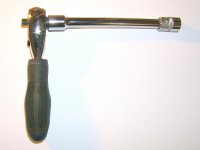
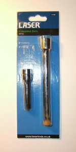
Top rear bolt: Working from under the car... 3/8" drive 13mm socket, on the end of a 6" 3/8" drive extension (Laser 1145 Extension Bars 3/8" Drive 2pc, 6" (145mm) and 3" (70mm), £5 local partstealer), and my stubby combination 3/8" and 1/4" drive wrench (£3 Homebase, bargain!) (See pics). This arrangement works perfectly with this bolt, with the wrench fitting nicely just to the left of the oil dipstick tube. I managed to undo this bolt with the rear mount still attached and with one (right) hand. Very tight at first then easy to turn.
Bottom bolt: Working from under the car... 3/8" drive 13mm socket on the end of my stubby wrench. No extension required. Easy.
Disconnected and withdrew NS driveshaft from gearbox/differential:
Notes for Novices Section 26 Disconnect NS drive shaft: I had already tackled the 6 NS driveshaft bolts in an earlier post in this thread (See above).
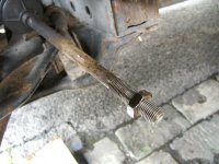
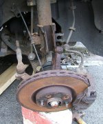
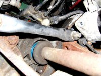
Notes for Novices Section 27 Break the NS suspension: As stated in thread Clutch Replacement - Additional Notes, there is no need to undo the drop link or tie rod/track rod end. I just undid the 2 hub to strut bolts. When you withdraw the hub from the strut the NS driveshaft pulls away from the gearbox. Sorted. The hub to strut nuts were quite tight - I used a 4 ft breaker bar on the end of my wrench. I then whacked the end of the bolts with a mallet and hammer to drive the them out of the strut. Tip: Support the hub BEFORE you try to remove the bolts as this takes the load off the bolts (See pics).
Disconnected and withdrew complete OS driveshaft from gearbox/differential:
Notes for Novices Section 22 Release OS inner driveshaft bearing: Followed N4N instructions: 10mm socket on my stubby wrench for the 3 10mm screws/bolts.
Notes for Novices Section 28 Break the OS suspension: Same as NS above - just undo the 2 hub to strut bolts.
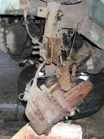
Notes for Novices Section 29 Withdraw the whole OS driveshaft...: Once the hub is disconnected from the strut, a pull on the hub pulls the OS outer and inner drive shafts out. When I checked the OS inner driveshaft bearing from under the car, it had moved 2" (5cm) towards the OS. Hoping that this is enough to clear the OS inner driveshaft from the gearbox/differential/bellhousing. Will find out tomorrow (See pics).
A few observations...
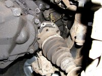
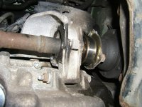
Just looking at the pics I took, I didn't realise that the OS gearbox driveshaft seal is on the outside of the clutch/gearbox bellhousing so presumably the seal can be replaced without detaching/removing the bellhousing? So it's not urgent to replace the seal during the clutch replacement procedure (if it looks OK)? (See pic).
Two problems I had expected and feared, described by other forum-ers: 1) Trouble withdrawing the hub from the strut and 2) Trouble withdrawing the OS driveshaft, requiring a puller - fortunately didn't materialize. The suspension breaking/driveshaft removal went without a hitch: Once the 2 hub-strut bolts were removed, the hubs virtually dropped from the struts, and no force was required to pull out the NS or OS driveshafts. Relief.
Mark
Had a very good day Yesterday. Felt I had made some real progress...
- Safely supported car on axle stands and Fiat car jacks.
- Removed all 3 starter motor bolts.
- Disconnected and withdrew NS driveshaft from gearbox/differential.
- Disconnected and withdrew complete OS driveshaft from gearbox/differential.
Safely supported car on axle stands and Fiat car jacks: I spent a long time getting the car as safe as possible with the load eventually borne by 2 x 3T axle stands near to the front jacking points under the longitudinal beams parallel to the sill beams, backed up by the 2 Fiat jacks under the longitudinal beams at the sills. Bounced the car up and down, side to side, and back and forth to test. More solid than just the jacks alone. A little disconcerting though hearing the supporting wood and rear tyres creak as I slowly jacked things up. The rear tyres are chocked front and rear, with the NS rear front chock backed up by another chock - a piece of wood nailed to a crack in the pavement edge. I'll do the same for the OS rear tomorrow. Don't want to nail into the road tarmac, the council wouldn't like that, but I'll fashion something...
Notes for Novices Section 2 Jack up the car and support on axle stands so the front sub-frame is 400mm above the floor: I think when I measured this with a tape measure I have the subframe 450mm above the deck, so should be no problem there I hope.
Removed all 3 starter motor bolts: A big stumbling block this until you have the solution, or 3 solutions, one for each bolt.
Top bolt nearest the front of the car: Working from above the engine... I used the device I described in an earlier post to sort this bolt.
Top rear bolt: Working from under the car... 3/8" drive 13mm socket, on the end of a 6" 3/8" drive extension (Laser 1145 Extension Bars 3/8" Drive 2pc, 6" (145mm) and 3" (70mm), £5 local partstealer), and my stubby combination 3/8" and 1/4" drive wrench (£3 Homebase, bargain!) (See pics). This arrangement works perfectly with this bolt, with the wrench fitting nicely just to the left of the oil dipstick tube. I managed to undo this bolt with the rear mount still attached and with one (right) hand. Very tight at first then easy to turn.
Bottom bolt: Working from under the car... 3/8" drive 13mm socket on the end of my stubby wrench. No extension required. Easy.
Disconnected and withdrew NS driveshaft from gearbox/differential:
Notes for Novices Section 26 Disconnect NS drive shaft: I had already tackled the 6 NS driveshaft bolts in an earlier post in this thread (See above).
Notes for Novices Section 27 Break the NS suspension: As stated in thread Clutch Replacement - Additional Notes, there is no need to undo the drop link or tie rod/track rod end. I just undid the 2 hub to strut bolts. When you withdraw the hub from the strut the NS driveshaft pulls away from the gearbox. Sorted. The hub to strut nuts were quite tight - I used a 4 ft breaker bar on the end of my wrench. I then whacked the end of the bolts with a mallet and hammer to drive the them out of the strut. Tip: Support the hub BEFORE you try to remove the bolts as this takes the load off the bolts (See pics).
Disconnected and withdrew complete OS driveshaft from gearbox/differential:
Notes for Novices Section 22 Release OS inner driveshaft bearing: Followed N4N instructions: 10mm socket on my stubby wrench for the 3 10mm screws/bolts.
Notes for Novices Section 28 Break the OS suspension: Same as NS above - just undo the 2 hub to strut bolts.
Notes for Novices Section 29 Withdraw the whole OS driveshaft...: Once the hub is disconnected from the strut, a pull on the hub pulls the OS outer and inner drive shafts out. When I checked the OS inner driveshaft bearing from under the car, it had moved 2" (5cm) towards the OS. Hoping that this is enough to clear the OS inner driveshaft from the gearbox/differential/bellhousing. Will find out tomorrow (See pics).
A few observations...
Just looking at the pics I took, I didn't realise that the OS gearbox driveshaft seal is on the outside of the clutch/gearbox bellhousing so presumably the seal can be replaced without detaching/removing the bellhousing? So it's not urgent to replace the seal during the clutch replacement procedure (if it looks OK)? (See pic).
Two problems I had expected and feared, described by other forum-ers: 1) Trouble withdrawing the hub from the strut and 2) Trouble withdrawing the OS driveshaft, requiring a puller - fortunately didn't materialize. The suspension breaking/driveshaft removal went without a hitch: Once the 2 hub-strut bolts were removed, the hubs virtually dropped from the struts, and no force was required to pull out the NS or OS driveshafts. Relief.
Mark
Attachments
Last edited:
Check the strut-hub bolts for stretch. As you say, they are tight and take quite a load. Look for a wasting/thinning towards the shank end of the threaded part. Don't be tempted to refit the old ones if they have stretched. This is the kind of thing a garage wouldn't even take a second look at, so abuse the privilege you're afforded by doing the work yourself & take the time to check things out.
Fiat part number is 7676615. Unfortunately, Fiat only sell them in packs of 5 (stupid, I know - you'd think they'd know how many there are on one of their cars!) and they're not cheap (around £13+VAT for the 5 last time I bought some from Shop4Parts) but they are a 'special' bolt so using a standard pattern one isn't ideal. I noticed you can buy them individually here:
http://www.eurocarcare.net/front-suspension/ecc7676615-bolt-front-strut-to-hub-carrier.html
If you buy them there, make sure you buy the nuts linked to on the same page. From Fiat, they cost more than the bolts!
Last edited:
Don't be tempted to refit the old ones if they have stretched
The thought did cross my mind as they look pretty old/knackered.
This is the kind of thing a garage wouldn't even take a second look at...
Do you mean they would automatically replace the bolts?
...so abuse the privilege you're afforded by doing the work yourself
I wouldn't call it a 'privilege'. I'd call it bl**dy hard work!
Fiat part number is 7676615... etc.
Thanks I follow those up.
From the top:
1. If the threaded section looks stretched, replace it. Those two bolts are holding on to the wheel for you.
2. No, just the opposite. Unless something is obviously failing, a garage won't want to prolong a job, by waiting for yet more parts to be delivered, more than absolutely necessary. They are a business not a charity, so the originals will go back on.
3. Your progress is, to put it politely, 'pedestrian' by the standards of a garage workshop. Don't start up in business as a mechanic!. HOWEVER, you are taking lots of photos which I know slows things down quite a bit, and you're being extremely careful & thorough, which is to your credit . Keep going - make the push to get the gearbox out, then you'll feel like you're getting somewhere. Go for it! I'd remove the gearbox, not just shift it to the side, then you can have a look at the input shaft bearing - again, something that most garages won't even give a first let alone second look.
4. ePER is down on the forum atm, but it's a very useful reference so make the most of it. I've got part numbers & prices for a lot of the often-replaced parts, along with best sources for them, so if you get stuck, ask away.
1. If the threaded section looks stretched, replace it. Those two bolts are holding on to the wheel for you.
2. No, just the opposite. Unless something is obviously failing, a garage won't want to prolong a job, by waiting for yet more parts to be delivered, more than absolutely necessary. They are a business not a charity, so the originals will go back on.
3. Your progress is, to put it politely, 'pedestrian' by the standards of a garage workshop. Don't start up in business as a mechanic!
. HOWEVER, you are taking lots of photos which I know slows things down quite a bit, and you're being extremely careful & thorough, which is to your credit . Keep going - make the push to get the gearbox out, then you'll feel like you're getting somewhere. Go for it! I'd remove the gearbox, not just shift it to the side, then you can have a look at the input shaft bearing - again, something that most garages won't even give a first let alone second look.4. ePER is down on the forum atm
, but it's a very useful reference so make the most of it. I've got part numbers & prices for a lot of the often-replaced parts, along with best sources for them, so if you get stuck, ask away.Just a quick update as it's been a long day...
The gearbox is out of the car! The procedure went OK. I followed Clutch Replacement - Additional Notes to manoeuver the gearbox out of the car, but dropped the front NS subframe about 1cm to get the gearbox over it. I can confirm that the damage is a disintegrated release bearing, at least. Can't tell if there's any damage to the (Valeo) clutch/flywheel yet. Very mucky bellhousing inside and out.
And my Mark I (no pun intended) DIY lifting/shifting device performed admirably on it's first outing. It lowered the bellhousing to the ground no problem.
More details later.
Mark
Last edited:
- Joined
- Feb 1, 2008
- Messages
- 755
- Points
- 175
Yep..deffo check for any play in the input shaft as mine gave out at Christmas!
Latest update for the last three days...
- The long stud
- Removing the gearbox
- Surveying the damage
Note: I didn't take many pics because the batteries ran out on my camera.
Day 1:
The long stud
Notes for Novices Section 23 Remove the long stud: On the first of the three days, I came unstuck as I couldn't remove the long top stud.The nut came off the stud no problem, but the second nut, required to remove the stud and taken from the lower stud, became stuck on it's stud - the lower nut AND stud came out of the bellhousing together as I undid the nut. The nut was stuck fast due to thread lock and the nut was the locking type with a spring-metal collar around the top. I tried gripping the unthreaded part of the stud with molegrips to no avail. A neighbour - who lent me his Transit jack to support the engine, thanks A. - suggested heating the nut and stud red hot -err how?, plastering with WD40 and trying again. Got them hot on the only thing available to me - my camping stove, and used WD40 and Plusgas but still no joy. Sh*t I thought, now I'll have to lower the front subframe. So the day ended badly...
Day 2:
The next day first thing I tried again. Much better grip on the stud this time, but maybe the penetrating oil had done it's job overnight, and the nut began to turn... Hooray! Cleaned up the stud thread with a wire brush.
Now for the top stud. Top stud nut screwed on first, then the lower stud nut. Spanner on the second nut and the top stud came out easily. I think the spring collar on the second nut helped to lock it into place on the stud.
Note: Notes for Novices Section 20 says that the upper and lower stud are 18mm and 19mm respectively - mine were BOTH 19mm.
Removing the gearbox
So off we go...
Notes for Novices Section 21 Remove the rear mounting, paragraph iv: Note: As Additional Notes states, there is no need to touch the long bolt in the centre of the mount. The mount came off easy peasy. Also very obvious once rear mount is removed how much easier it is to see and access the starter motor.
Notes for Novices Section 22 Release OS inner driveshaft bearing: Already done this.
Notes for Novices Section 23 Remove the long stud: Already done.
Notes for Novices Section 24 Remove the starter motor bolts: Already done this. As Additional Notes states: leave the starter motor bolts until the rear mount is off.
Notes for Novices Section 25 Drain the gearbox oil: Already done.
Notes for Novices Section 26 Disconnect NS drive shaft: Already done this.
Notes for Novices Section 27 Break the NS suspension: Not necessary in my opinion, but... I had already undone the track rod end earlier which maybe gave me more hub movement to move the NS driveshaft right out of the way at gearbox removal. Also wondered whether the drop link was holding up the anti-roll bar thus preventing the NS front subframe from dropping, so I undid the top drop link joint (very very tight to undo, gave the junior hacksaw a day off !)
Notes for Novices Section 28 Break the OS suspension: Didn't do it.
Notes for Novices Section 29 Withdraw the whole OS driveshaft...: Once Section 22 is done, all but 1/2" (12mm) of OS inner driveshaft came out of the OS gearbox driveshaft seal, so thought that was OK.
Notes for Novices Section 30 Support engine on hydraulic jack and disconnect the earth: Did both. Borrowed my neighbour's Transit scissor jack with block of wood under gearbox end of sump. Levelled the road camber underneath engine with more wood and chocks.
Notes for Novices Section 30 (remove the front gearbox support): Bolts and mount came out easily once started. Also as stated in Additional Notes I didn't undo the mount central bolt but instead the 3 x 13mm bolts which fix the mount to the chassis.
Notes for Novices Section 31 Loosen bolts and separate the clutch bell-housing from the engine: No problem. Very tight then easy once started. Nearly rounded Notes for Novices Section 20 Bolt (a), 13mm, NS because couldn't get my socket and wrench on it properly - sh***************t. Nearly came unstuck.
Once all the bolts were loosened to about 1" (25mm) (I found that most bolts were unscrewed completely at 25mm) used my little prybar to pry open the bellhousing, but it was hardly required as the bellhousing was quite easy to detach. Left the flywheel access plate on.
Notes for Novices Section 32 Lower front subframe: Top stud removed earlier (hooray!) so no need to drop subframe or... see below...
Notes for Novices Section 33 Lower clutch bellhousing...: So I assembled my DIY lifting/shifting device in/on top of the engine bay, wrapped a 1m chain round the gearbox and secured it with a snazzy carabiner (pics later), then attached the hoist to the carabiner, and began lowering... I was following Additional Notes so to get the gearbox out you have to rotate it - looking through the NS wheelarch - ANTICLOCKWISE to lift the gearbox over the front subframe. Nearly made it, very tight, but found that I couldn't get the gearbox over the left bolt and nut of the NS wishbone bush. Also note that the gearbox lever balls get uncomfortably close at the top to brake pipes, so watch out. So I undid the 3 NS subframe bolts (N4N Section 32, diagram: NS 18, 20a, 20b) about 1/2" (12/13mm). This allowed the subframe to drop about 1cm which gave enough clearance to lift the gearbox over the subframe. (Sorry if I sound repetitive, but I think stating things clearly is more important than not being repetitive).
The rest of the gearbox lowering process was just fiddling around with my hoist to avoid various pipes in the engine bay. I added another carabiner to the hoist when the gearbox was lower down to get the box right down to the ground. I was very happy with the hoist. It became more solid once it had a load on it (not that it was flimsy beforehand). It includes a big - but cheap - support beam which I thought I would have to rope back to prevent it sliding back and forth, but no rope was required. The support beam can be moved front-to-back and side-to-side, it stays put once it's moved into position, and the hoist - a 1m M8 rod with a nut and washers on the rod above the support beam, and a block and shackle at the bottom of the rod - provides the up-down motion.
Once on the ground I was able to pick up the gearbox using the bottom carabiner as a grab handle.
Phew!
Day 3 :
Surveying the damage
With everything off, here's my amateur verdict (Note: all Valeo kit)...
Release bearing: Completely mangled.
Clutch plate: Friction material is very worn down, with small cracks visible on the surface. Otherwise it looks fairly intact.
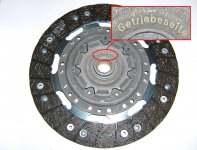
Clutch cover: Looks in good condition - I'd reuse it! For those interested, the clutch fingers are really sturdy compared to my LUK version, about twice the width at the tips (But does more spring resistance in the fingers mean that the clutch is stiffer/requires more force to operate? Conversely do thinner fingers mean they can break more easily?). The wear on the fingers is uneven with more wear on one side of the circle of clutch fingers than the other. Wonder why?
Flywheel: Can't tell if it's a DMF or single mass flywheel because whatever it is it appears to be seized. Valeo UK (T. 01527 838300 or 01527 516910) couldn't tell me either because they only have recent part numbers. Very helpful guy though: he said the clutch cover bolts are not stretch and can be reused and he gave me the PN for the replacement Valeo kits (too late mate I've gone all LUK). He also said that to test the DMF flywheel - rotationally you should not be able to move the inner vs outer mass more than 5 flywheel teeth, and on a flat surface it should not rock more than a 2-3 mm side-to-side.
Input shaft: Can't detect any play and no sign of leakage.
OS gearbox oil seal: No sign of leakage. So won't touch.
Clutch fork: Doesn't look too bad. Not too much play. Looks easy enough to replace the 2 bearings. Should be even better with new bearings in. Will let you know.
Bought a load of cleaning kit - including a bath for the gearbox - well it only gets a bath a few times in it's lifetime (by the way, before you jump on me, the bath is to collect the dirty cleaning fluid to take to the tip not pour down the drain!). So tomorrow, it'll be scrub, scrub, scrub, a gearbox in a tub. After I've played around removing the DMF/SMF bolts and flywheel.
Didn't get much else done because work stopped play.
Mark
- The long stud
- Removing the gearbox
- Surveying the damage
Note: I didn't take many pics because the batteries ran out on my camera.
Day 1:
The long stud
Notes for Novices Section 23 Remove the long stud: On the first of the three days, I came unstuck as I couldn't remove the long top stud.The nut came off the stud no problem, but the second nut, required to remove the stud and taken from the lower stud, became stuck on it's stud - the lower nut AND stud came out of the bellhousing together as I undid the nut. The nut was stuck fast due to thread lock and the nut was the locking type with a spring-metal collar around the top. I tried gripping the unthreaded part of the stud with molegrips to no avail. A neighbour - who lent me his Transit jack to support the engine, thanks A. - suggested heating the nut and stud red hot -err how?, plastering with WD40 and trying again. Got them hot on the only thing available to me - my camping stove, and used WD40 and Plusgas but still no joy. Sh*t I thought, now I'll have to lower the front subframe. So the day ended badly...
Day 2:
The next day first thing I tried again. Much better grip on the stud this time, but maybe the penetrating oil had done it's job overnight, and the nut began to turn... Hooray! Cleaned up the stud thread with a wire brush.
Now for the top stud. Top stud nut screwed on first, then the lower stud nut. Spanner on the second nut and the top stud came out easily. I think the spring collar on the second nut helped to lock it into place on the stud.
Note: Notes for Novices Section 20 says that the upper and lower stud are 18mm and 19mm respectively - mine were BOTH 19mm.
Removing the gearbox
So off we go...
Notes for Novices Section 21 Remove the rear mounting, paragraph iv: Note: As Additional Notes states, there is no need to touch the long bolt in the centre of the mount. The mount came off easy peasy. Also very obvious once rear mount is removed how much easier it is to see and access the starter motor.
Notes for Novices Section 22 Release OS inner driveshaft bearing: Already done this.
Notes for Novices Section 23 Remove the long stud: Already done.
Notes for Novices Section 24 Remove the starter motor bolts: Already done this. As Additional Notes states: leave the starter motor bolts until the rear mount is off.
Notes for Novices Section 25 Drain the gearbox oil: Already done.
Notes for Novices Section 26 Disconnect NS drive shaft: Already done this.
Notes for Novices Section 27 Break the NS suspension: Not necessary in my opinion, but... I had already undone the track rod end earlier which maybe gave me more hub movement to move the NS driveshaft right out of the way at gearbox removal. Also wondered whether the drop link was holding up the anti-roll bar thus preventing the NS front subframe from dropping, so I undid the top drop link joint (very very tight to undo, gave the junior hacksaw a day off !)
Notes for Novices Section 28 Break the OS suspension: Didn't do it.
Notes for Novices Section 29 Withdraw the whole OS driveshaft...: Once Section 22 is done, all but 1/2" (12mm) of OS inner driveshaft came out of the OS gearbox driveshaft seal, so thought that was OK.
Notes for Novices Section 30 Support engine on hydraulic jack and disconnect the earth: Did both. Borrowed my neighbour's Transit scissor jack with block of wood under gearbox end of sump. Levelled the road camber underneath engine with more wood and chocks.
Notes for Novices Section 30 (remove the front gearbox support): Bolts and mount came out easily once started. Also as stated in Additional Notes I didn't undo the mount central bolt but instead the 3 x 13mm bolts which fix the mount to the chassis.
Notes for Novices Section 31 Loosen bolts and separate the clutch bell-housing from the engine: No problem. Very tight then easy once started. Nearly rounded Notes for Novices Section 20 Bolt (a), 13mm, NS because couldn't get my socket and wrench on it properly - sh***************t. Nearly came unstuck.
Once all the bolts were loosened to about 1" (25mm) (I found that most bolts were unscrewed completely at 25mm) used my little prybar to pry open the bellhousing, but it was hardly required as the bellhousing was quite easy to detach. Left the flywheel access plate on.
Notes for Novices Section 32 Lower front subframe: Top stud removed earlier (hooray!) so no need to drop subframe or... see below...
Notes for Novices Section 33 Lower clutch bellhousing...: So I assembled my DIY lifting/shifting device in/on top of the engine bay, wrapped a 1m chain round the gearbox and secured it with a snazzy carabiner (pics later), then attached the hoist to the carabiner, and began lowering... I was following Additional Notes so to get the gearbox out you have to rotate it - looking through the NS wheelarch - ANTICLOCKWISE to lift the gearbox over the front subframe. Nearly made it, very tight, but found that I couldn't get the gearbox over the left bolt and nut of the NS wishbone bush. Also note that the gearbox lever balls get uncomfortably close at the top to brake pipes, so watch out. So I undid the 3 NS subframe bolts (N4N Section 32, diagram: NS 18, 20a, 20b) about 1/2" (12/13mm). This allowed the subframe to drop about 1cm which gave enough clearance to lift the gearbox over the subframe. (Sorry if I sound repetitive, but I think stating things clearly is more important than not being repetitive).
The rest of the gearbox lowering process was just fiddling around with my hoist to avoid various pipes in the engine bay. I added another carabiner to the hoist when the gearbox was lower down to get the box right down to the ground. I was very happy with the hoist. It became more solid once it had a load on it (not that it was flimsy beforehand). It includes a big - but cheap - support beam which I thought I would have to rope back to prevent it sliding back and forth, but no rope was required. The support beam can be moved front-to-back and side-to-side, it stays put once it's moved into position, and the hoist - a 1m M8 rod with a nut and washers on the rod above the support beam, and a block and shackle at the bottom of the rod - provides the up-down motion.
Once on the ground I was able to pick up the gearbox using the bottom carabiner as a grab handle.
Phew!
Day 3 :
Surveying the damage
With everything off, here's my amateur verdict (Note: all Valeo kit)...
Release bearing: Completely mangled.
Clutch plate: Friction material is very worn down, with small cracks visible on the surface. Otherwise it looks fairly intact.
Clutch cover: Looks in good condition - I'd reuse it! For those interested, the clutch fingers are really sturdy compared to my LUK version, about twice the width at the tips (But does more spring resistance in the fingers mean that the clutch is stiffer/requires more force to operate? Conversely do thinner fingers mean they can break more easily?). The wear on the fingers is uneven with more wear on one side of the circle of clutch fingers than the other. Wonder why?
Flywheel: Can't tell if it's a DMF or single mass flywheel because whatever it is it appears to be seized. Valeo UK (T. 01527 838300 or 01527 516910) couldn't tell me either because they only have recent part numbers. Very helpful guy though: he said the clutch cover bolts are not stretch and can be reused and he gave me the PN for the replacement Valeo kits (too late mate I've gone all LUK). He also said that to test the DMF flywheel - rotationally you should not be able to move the inner vs outer mass more than 5 flywheel teeth, and on a flat surface it should not rock more than a 2-3 mm side-to-side.
Input shaft: Can't detect any play and no sign of leakage.
OS gearbox oil seal: No sign of leakage. So won't touch.
Clutch fork: Doesn't look too bad. Not too much play. Looks easy enough to replace the 2 bearings. Should be even better with new bearings in. Will let you know.
Bought a load of cleaning kit - including a bath for the gearbox - well it only gets a bath a few times in it's lifetime (by the way, before you jump on me, the bath is to collect the dirty cleaning fluid to take to the tip not pour down the drain!). So tomorrow, it'll be scrub, scrub, scrub, a gearbox in a tub. After I've played around removing the DMF/SMF bolts and flywheel.
Didn't get much else done because work stopped play.
Mark
Last edited:
Good progress! I bet you're chuffed to bits right now!
Check the input bearing carefully for play. It needs quite a hefty pull around. Sounds as though you've got away with it though - the tell tale is leaking gearbox oil from the seal.
Pictures of the clutch fingers please! Btw, I think the JTD was only ever supplied with a DMF. That's why people can't get hold of a solid one to replace them. I think they're mad to weld them up anyway - the DMF does a good job of damping out low frequency vibration from the engine.
Similar threads
- Replies
- 12
- Views
- 439
- Replies
- 10
- Views
- 982