OP
OP
I decided to have a go at fabricating the inner wing panel. I wanted to get this part sorted so I could finish the ns first, I didn't really want to start another part of the vehicle as it can get a bit daunting when there is so much to do. Far better to concentrate on one area first.
Step 1. Planning.
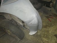
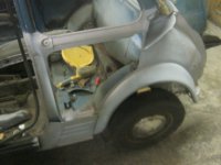
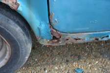
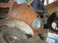
The inner wing is rotten at the bottom (usual place to corrode).
There is a good solid centre section which I can leave in place.
The Top section is very curved and also has a more bulbess section where it meets the bulkhead, only reason I could see for this was to allow for more room for the wiring loom to come through. The upright section where the 1/4 joins to is heavily corroded.
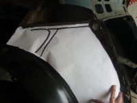
I made some paper templates to get the size of the metal parts required.
Unfortunately I don't have the tools or expertise to make a panel out of one piece of steel so I will need to make it in sections.
Step 2. Cut & shape panels.
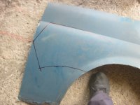
I conveniently had a 1/4 panel that I cut off that had similar shaping to the parts I required. Its always easier to shape metal that is similar shape than to start with a flat sheet.
I cut the sections out & cleaned the metal of paint, filler, rust & other stuff.
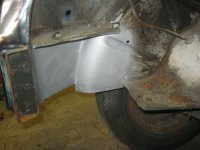
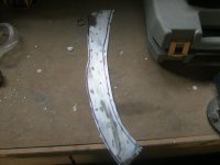
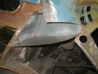
Starting with the upright panel I folded the edge over to resemble the original.
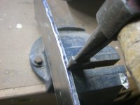
This caused the panel to bow so I used the edge of the hammer to shrink the edge (I daren't buy a shrinker at the moment, wifes asking questions!), then folded the other side which didn't bow the panel.
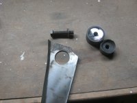
There is a large hole at the top, a lot bigger than my cutters, then I remembered a hole cutter I had for stainless steel sinks which came with a sink from IKEA about 10 years ago. Perfect size!
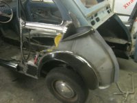
I cut off the original upright section and tacked in the new one. I then tried the 1/4 & Engine cover/boot & rear panel. All lined up ok.
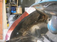
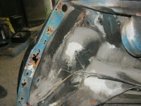
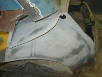
I then formed up 2 panels to make the main inner wing section & removed the other part of the inner wing & cleaned up surrounding areas and straightened surfaces up.
The flat section above was fairly corroded, I tried cleaning it but due to access this was going to be difficult, so I cut it off & made a new one.
This was so much quicker & cleaner & also gave me access to clean the inside section.
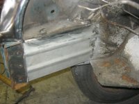
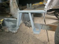
I then formed a right angle section that will be spot welded to the underneath & then the other 2 panels can be welded to it. Clamped this in place and then trimmed the other panels up to fit better and held them all in place with self tappers.
Step 3. Weld it up
When happy with the fit I removed it in one section & welded it together.
Disaster happened @ 7.20pm, I ran out of mig wire. Down to Halfords, bought new wire, spare C02 bottle just in case and got back home at 7.50 to finish it off.
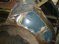
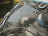
Gave it a good grind up, little bit more dressing up from heat distortion & spot welded & migged in place.
I don't know why but my mig started playing up once I change the wire (might be a dodgy reel) I will check this out later because I struggled to get a clean weld from it. It might also be because I used a zinc primer!
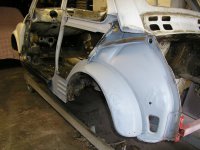
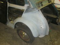
Anyway, a good clean up & a coat of zinc primer & Hey Presto its as good as new. Just need to do the bottom section now.

Step 1. Planning.
The inner wing is rotten at the bottom (usual place to corrode).
There is a good solid centre section which I can leave in place.
The Top section is very curved and also has a more bulbess section where it meets the bulkhead, only reason I could see for this was to allow for more room for the wiring loom to come through. The upright section where the 1/4 joins to is heavily corroded.
I made some paper templates to get the size of the metal parts required.
Unfortunately I don't have the tools or expertise to make a panel out of one piece of steel so I will need to make it in sections.
Step 2. Cut & shape panels.
I conveniently had a 1/4 panel that I cut off that had similar shaping to the parts I required. Its always easier to shape metal that is similar shape than to start with a flat sheet.
I cut the sections out & cleaned the metal of paint, filler, rust & other stuff.
Starting with the upright panel I folded the edge over to resemble the original.
This caused the panel to bow so I used the edge of the hammer to shrink the edge (I daren't buy a shrinker at the moment, wifes asking questions!), then folded the other side which didn't bow the panel.
There is a large hole at the top, a lot bigger than my cutters, then I remembered a hole cutter I had for stainless steel sinks which came with a sink from IKEA about 10 years ago. Perfect size!
I cut off the original upright section and tacked in the new one. I then tried the 1/4 & Engine cover/boot & rear panel. All lined up ok.
I then formed up 2 panels to make the main inner wing section & removed the other part of the inner wing & cleaned up surrounding areas and straightened surfaces up.
The flat section above was fairly corroded, I tried cleaning it but due to access this was going to be difficult, so I cut it off & made a new one.
This was so much quicker & cleaner & also gave me access to clean the inside section.
I then formed a right angle section that will be spot welded to the underneath & then the other 2 panels can be welded to it. Clamped this in place and then trimmed the other panels up to fit better and held them all in place with self tappers.
Step 3. Weld it up
When happy with the fit I removed it in one section & welded it together.
Disaster happened @ 7.20pm, I ran out of mig wire. Down to Halfords, bought new wire, spare C02 bottle just in case and got back home at 7.50 to finish it off.
Gave it a good grind up, little bit more dressing up from heat distortion & spot welded & migged in place.
I don't know why but my mig started playing up once I change the wire (might be a dodgy reel) I will check this out later because I struggled to get a clean weld from it. It might also be because I used a zinc primer!
Anyway, a good clean up & a coat of zinc primer & Hey Presto its as good as new. Just need to do the bottom section now.
Attachments
-
 IMG_4488.JPG351.2 KB · Views: 71
 -
 IMG_4489.JPG444.2 KB · Views: 68
 -
 IMG_4492.JPG516.9 KB · Views: 75
 -
 IMG_4493.JPG363.1 KB · Views: 74
 -
 IMG_4494.JPG353.8 KB · Views: 73
 -
 IMG_4477.JPG502 KB · Views: 78
 -
 IMG_4507.JPG466 KB · Views: 80
 -
 IMG_4505.JPG455.2 KB · Views: 77
 -
 IMG_4504.JPG495.2 KB · Views: 76
 -
 IMG_4499.JPG519.1 KB · Views: 68
 -
 IMG_4512.JPG433.5 KB · Views: 80
 -
 IMG_4511.JPG445.3 KB · Views: 71
 -
 IMG_4478.JPG549.1 KB · Views: 76
")