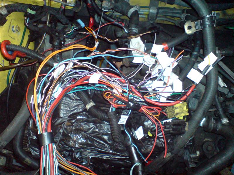
do you know which wire is for the fuel pump. ive got two left, one orange and one orange and green.
The fuel pump wire running from the fuel pump relay to the ECU is Orange.


do you know which wire is for the fuel pump. ive got two left, one orange and one orange and green.
the fuel pump relay is part of the main fuel injection relay isn't it.
ive binned all that. i need the wire that goes from the fuel pump relay to the pump. the wire that actually powers the pump.
there are two that go from the main relay, to the loom and then they go into the connector that connect the engine loom to the body loom. one is orange, the other is orange and green.
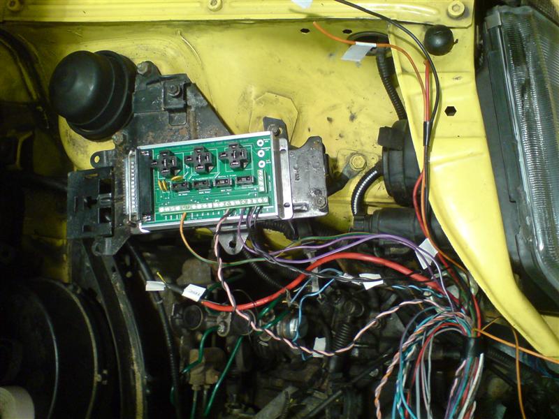
Q: Which case is used for board mounting?
A: The Relay/Power board uses one half of a LMB EAS-200. The case comes apart in halves (top and bottom) when you remove the end plates. The Relay/Power PCB slides into one of the case halves, and is held in place with the end plates - one plate is cut in half and used on both sides. The top of the LMB case is not tall enough to clear the relays, so it is not used.
Q: So, this means that the top of the board is exposed?
A: Yes, but this is acceptable in a engine bay environment. The unit is mounted underhood, so the likelihood of accidential shorts, contacts to foriegn objects, etc. is the same as with any other engine component (starter, alternator, fuse block, etc). The PCB has a soldermask layer which will provide some protection, and the user can coat the finished board with conformal coating or polyurethane before mounting in the case. In addition, all circuits are fused, so an accidential contact will cause a fuse or polyswitch device to open. One thing to remember is to drill a small (1/8") hole in the bottom-side of the case to allow the escape of moisture from the backside of the PCB/case interior
")
Prefer not to thanks :yuck:**** me i'm good.