General Brought a 2002 Stilo JTD as a project ...

Currently reading:
General Brought a 2002 Stilo JTD as a project ...

Sure, looks fairly bread and butter:)
Should be able to do a quick turnaround for you, let me know when you have the new chips in your hand

Thats great Decks, if plan A fails I'll be in touch.

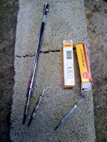
In a former life I used this on a daily basis for chip removal with consistent success Shadey :- http://www.wiresandstuff.com/tools/servisol-soldamop-no-clean-desolder-braid-wick-sucker.html

Re-soldering is made much easier with an electric soldering iron with a fine tip, just be sure to get the heat into the PC board & let the solder melt into that, it will migrate on to the chip legs like magic if you use a fine solder that contains its own flux.

Thats a really usefull product, I've saved the link, thanks.

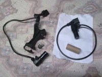
Shadey do you have the part number for the body computer?

I've refitted it to the car now(so I know where everything is) but I wrote the part number down somewhere I'll post it up as soon as I find it.

Can I ask why you want it?
 
Last edited:
Thats great Decks, if plan A fails I'll be in touch.


I've refitted it to the car now(so I know where everything is) but I wrote the part number down somewhere I'll post it up as soon as I find it.

Can I ask why you want it?

A friend of mine has a Fiat mechanic friend and he may be able to source a used one. Not sure if a LHD control unit is any different? But basically as deckchair said it can be done but it may not be the original problem, but if you can get someone to do it, worth a try. I will let you know if I can source a part from here.
 
The number I wrote down was the updated part number 51755131 - BODY COMPUTER

If you need the old part number I'll have to remove the BC from the car again?

That should do it for now, no need to go through the removal of the old phone if I cant get one here.
 
Can you not just contact a few breakers and ask for the bc with keys then swap the transponders? Sounds the simplest plan to me but probably not the cheapest.
 
I was wondering how/why these relay chips would over heat and cause problems so I checked the bulbs in the rear lights. They're Osram. Could they have drawn more current and caused the chips to over heat and fail?

The spec. sheet for the chips says they are internally current limited at 15 Amps for each output. No matter what load you put on them, they should only allow 15 Amps to pass, unless the current limiting function is blown.

From your earlier picture, both chips look overheated. You can see the heat rings radiating out from them.

They are SMD (Surface Mount Devices) so would need to be removed and refitted to the PCB with a heat gun and solder paste. The solder wick mentioned earlier would not work because you need to unsolder all the pins at the same time to be able to lift the chips off the board.
 
Last edited:
The spec. sheet for the chips says they are internally current limited at 15 Amps for each output. No matter what load you put on them, they should only allow 15 Amps to pass, unless the current limiting function is blown.

From your earlier picture, both chips look overheated. You can see the heat rings radiating out from them.

They are SMD (Surface Mount Devices) so would need to be removed and refitted to the PCB with a heat gun and solder paste. The solder wick mentioned earlier would not work because you need to unsolder all the pins at the same time to be able to lift the chips off the board.

Thats plan B and I got it covered. (Decks ;))

Plan A is to replace the complete Body Computer and get the key recoded to it after I've used FES to do the Proxi-alignment proceedure.
 
Last edited:
Shadey, if you want i have access to professional soldering equipment (work in a radio engineering lab) and am more than capable of replacing those chips...should see the tincy stuff im normally poking.

So if you want, you can post me the BC and replacement chips and ill be happy to do the swap for you and post it back.

and from the pics, i cant tell if they've swollen? damn 2d!, but they are cooked.

Thanks for the offer but I've already got that covered, Decks has offered his help.

I've just brought another body computer from a 5 door 2003 Stilo Dynamic for £18.99 ... :D

I dont think the guy knew what he was selling as he had it listed as a fuse box. He obviously didn't know there is a £400 body computer clipped to the back of the fuse box. (y)

This guy is probabely doesn't know either as he's only suplying the part number for the distribution board(fusebox) and not for the BC.
http://www.ebay.co.uk/itm/FIAT-STILO-02-5-DOOR-1-6-INT-FUSE-BOX-/280700296861

Note to self: When searching eBay for a Body Computer search for Fuse Box instead, much cheaper and there's far more of them.
 
Last edited:
This post contains affiliate links which may earn a commission at no additional cost to you.
The spec. sheet for the chips says they are internally current limited at 15 Amps for each output. No matter what load you put on them, they should only allow 15 Amps to pass, unless the current limiting function is blown.

From your earlier picture, both chips look overheated. You can see the heat rings radiating out from them.

They are SMD (Surface Mount Devices) so would need to be removed and refitted to the PCB with a heat gun and solder paste. The solder wick mentioned earlier would not work because you need to unsolder all the pins at the same time to be able to lift the chips off the board.

Works fine on Surface mount chips & components, just do a side at a time. (y)
 
Works fine on Surface mount chips & components, just do a side at a time. (y)

In my work shop, we don't bother with heat guns etc to remove them....if they're coming off they're broken, so we just cut the legs carefully with a scalpel then you take them remaining legs off the pads with solder wick...clean up with IPA then have fun installing the new chip lol (dab of glue, very fine tip and patience)

Good luck shadey, could earn you a pretty penny, besides the knowledge gained (y)
 
Good luck shadey, could earn you a pretty penny, besides the knowledge gained (y)

She's a lovely clean car, would have been a shame to scrap her and beer tokens are always welcome. (y)


Well both glow plugs have now been replaced and the preheat fault has gone. :D

I was expecting it to be a difficult job because of what I'd read on here but everything was quite straight forward. Clipping the cables back onto the new glow plugs turned out to be my biggest problem.

Thanks Argo, couldn't have done it without your guide. (y)
 

Attachments

  • Image0050.jpg
    Image0050.jpg
    798.7 KB · Views: 118
  • Image0052.jpg
    Image0052.jpg
    712.6 KB · Views: 98
  • Image0054.jpg
    Image0054.jpg
    595.3 KB · Views: 94
  • Image0055.jpg
    Image0055.jpg
    718 KB · Views: 85
  • Image0057.jpg
    Image0057.jpg
    1,007.4 KB · Views: 90
Last edited:
Image 0050 looks like a mint engine Shadey! The whole under-bonnet area looks clean in fact, did you spruce it up?
 
Image 0050 looks like a mint engine Shadey! The whole under-bonnet area looks clean in fact, did you spruce it up?

I don't like dirty work spaces so yes I did give it a blast with the air hose but as I said earlier, she's a lovely car. She has 105,000 miles on the clock but doesn't show it. How many Stilos have you seen with the rubber seal still attached to the engine cover(the one that goes around the oil filler cap)? This one still has the oringinal seal in place.

If I manage to get her back to 100% I'll have a local mobile valeter give her a good going over then offer her up forsale.

Looks like she's been well looked after untill recently. I guess all the problems came at once and she almost ended up in a breakers yard.
 
Last edited:
Rain stopped play for a while but eventually got a dry 30 minutes to replace the Crank Sensor.

That dodgy crank sensor was making her run rough, she running beautifully now its been replaced.

Was awkward getting my big hands into the tight spaces below the starter motor but not impossible.

Edit.
Almost forgot.
An "O" ring comes with the new one, it needs to be inserted correctly into its slot or you'll have oil dripping everywhere. In the photo on the right you can just about see the slot in the hole.
 

Attachments

  • Image0058.jpg
    Image0058.jpg
    673.2 KB · Views: 64
  • Image0059.jpg
    Image0059.jpg
    1.5 MB · Views: 69
Last edited:
Back
Top