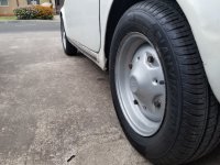
Phew! great to hear that it is all back in and running well. But, don't forget---you still have only drum brakes, and there is a fair chance that you will be tempted to drive the car more than a tad faster! If you can find them, try to get hold of a set of MK 1 '126' wheels. They have the same wheel-bolt spacing as the 500 (190 pcd), but are a shade wider.
I have got two of the early 126 wheel rims. As Tom says they are 1/2" wider than the 500 ones. I just sent them away for sand blasting to make them more saleable so they will be up for grabs when I get them back.
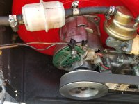
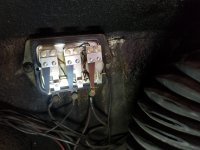
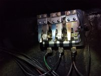
") It does look a bit dangerous, as both fuel pipes look split and you really don’t want it emptying out all over you electrics, as it could get a bit messy. The general consensus of opinion is they are not needed.
It does look a bit dangerous, as both fuel pipes look split and you really don’t want it emptying out all over you electrics, as it could get a bit messy. The general consensus of opinion is they are not needed.