- Joined
- May 9, 2020
- Messages
- 35
- Points
- 60
Hello,
No resolution so far, but some observations:
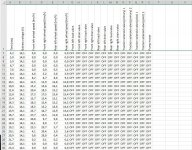
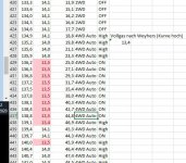
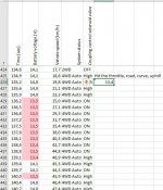
If the IBS is deactivated by pulling out the connector on the battery load sensor, the ABS is dead (cf. <NoLinNoABS.jpg>). This explains why I could observe a dip in voltage greater 0.5V when the coupling solenoid is engaging (cf. <CCMNoLin.jpg>) but could not observe a dip when observing the ABS controller.
What I did check is the ground pole on the battery. Just to exclude, that this is not resistance in row after everything.
Terminal (that is the one big ground connector) to car mass no resistance measurable when disconnected, no voltage measurable when connected. From the
False pole to battery pole no voltage drop, no resistance.
Battery pole to car mass no voltage, no resistance.
So, this part seems to be sound.
I took the battery out, charged it over night, cleaned the poles and installed everything as neatly as I can.
So next thing would be to check ground as seen from the ABS controller (anybody knows, where the Coupling Control Module is located?) to the battery pole.
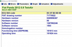
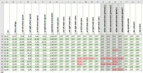
Am I right, that the ABS controller (which is one part with the hydraulic block, in the MultiEcusan it is called Bosch ABS ESP 9, cf. <abs9esp.png>) uses only the mass on the connector, or is this only used for the "intelligence" (vulgo: CAN and steering signals) ?
Looking at the pin usage it looks as if this is only "intelligence":
1. +
2. speed car (from CAN)
4. signal front right
8. signal front left
13. - (ground)
16. supply sensor front right
17. supply sensor rear right
18. signal rear left
19. supply sensor rear left
25. +
26. C CAN high
27. C CAN high
28. Line K
29. signal rear right
31. supply rear left
38. - ground
If ever the "work" has its own ground, my question would be where the ground for the pump and the valves is located. Or do they use the pins 38 and 13?
Any contribution appreciated!
Thx,
David
No resolution so far, but some observations:
If the IBS is deactivated by pulling out the connector on the battery load sensor, the ABS is dead (cf. <NoLinNoABS.jpg>). This explains why I could observe a dip in voltage greater 0.5V when the coupling solenoid is engaging (cf. <CCMNoLin.jpg>) but could not observe a dip when observing the ABS controller.
What I did check is the ground pole on the battery. Just to exclude, that this is not resistance in row after everything.
Terminal (that is the one big ground connector) to car mass no resistance measurable when disconnected, no voltage measurable when connected. From the
False pole to battery pole no voltage drop, no resistance.
Battery pole to car mass no voltage, no resistance.
So, this part seems to be sound.
I took the battery out, charged it over night, cleaned the poles and installed everything as neatly as I can.
So next thing would be to check ground as seen from the ABS controller (anybody knows, where the Coupling Control Module is located?) to the battery pole.
Am I right, that the ABS controller (which is one part with the hydraulic block, in the MultiEcusan it is called Bosch ABS ESP 9, cf. <abs9esp.png>) uses only the mass on the connector, or is this only used for the "intelligence" (vulgo: CAN and steering signals) ?
Looking at the pin usage it looks as if this is only "intelligence":
1. +
2. speed car (from CAN)
4. signal front right
8. signal front left
13. - (ground)
16. supply sensor front right
17. supply sensor rear right
18. signal rear left
19. supply sensor rear left
25. +
26. C CAN high
27. C CAN high
28. Line K
29. signal rear right
31. supply rear left
38. - ground
If ever the "work" has its own ground, my question would be where the ground for the pump and the valves is located. Or do they use the pins 38 and 13?
Any contribution appreciated!
Thx,
David