Irgendeiner
New member
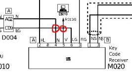
My Ducato has an electronic anti-theft system consisting of a round coil wrapped around the keyhole plate and a Bosch electronics box under the steering wheel, type "wfs 125f2."
Normally, when the engine is started, this system checks whether a key with an integrated chip and a specific number is inserted and then starts the engine.
Suddenly, the system no longer recognized the correct key. A yellow "missing key" symbol appeared on the dashboard. Although the engine was running, there was no ignition, and I couldn't drive home.
Fortunately, this demon disappeared the next day, and everything seemed fine, until I drove a short distance to the shops. Then the car wouldn't start again, and I had to walk home.
The technicians I knew didn't know what to do, so I went to the car the next day, and luckily, it worked again, and I was able to drive home.
But now I don't dare driving it anymore :-(
As an experienced electronics engineer, I could install a mechanical switch to bypass the faulty system, if only I could get the circuit diagrams for this chaotic system.
a) Has anyone ever experienced a similar situation? What did they do?
b) Does anyone have any tips on how to get the circuit diagrams?
Thanks and regards!
Irgendeiner
")