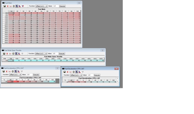
Technical IAW ECU Live Mapping & Tech Info

Currently reading:
Technical IAW ECU Live Mapping & Tech Info

Ok I understand.
I need to extend the lead to the OBD and run it through the cabin of the car, avoiding the HT leads and coils. I will try that.

It's more work than you think, but it also depends on how your car is stripped at the moment.

Finally, I am interested in which aftermarket ECU you would choose because the only reason for having the car is for motorsport purposes. You are right that I would probably end up having someone do all the work.

Personally I would not go for an aftermarket ECU, not even for a turbo application, I am crazy about playing with factory ECUs, but that's me. But apart from that, I'd suggest looking into ECU Master's EMU for a reasonably priced one, especially that this one (maybe others too) include some sport options (like launch control). But you have to do your homework here in terms of what you want, need, your budget, and the work required on the car. Setting up a standalone system is a bitch, you have to do all the wiring and set up the software practically from scratch. Done by oneself it takes a long time and lots of swearing, done by a specialist costs a small fortune.

Alternatively you can go for a good quality piggy back system like DET3 (also from ECU Master). Less wiring work, and very decent tuning options. And less work setting up software as you start from a running factory ECU and do your work on top of that.
 
X/125 for 18FD is pulse of a single injector opening, which happens 2 times per engine cycle with two injectors each time.

X/500 for 18F is again one pulse of a single injector, which happens 2 times per engine cycle with all four injectors each time.

X/500 for 16F is one pulse of a single (and the only) injector, which happens 4 times per engine cycle.
I don't have the IAW-18FD unit, but I've just written the CKP signal emulator (using Arduino) and tested injection timing on my test ECUs (IAW-16F.EB an IAW-8F.5T). Here are the results (sorry for Polish):
IAW-16F [reported: 2,68ms, measured: 3,37ms, 2 pulses/revolution]
5704284700_1452197207.png

7435502300_1452197263.png

5058302400_1452197263.png


IAW-8F [reported: 5,58ms, measured: 6,58ms, 1 pulse/revolution]
2867075300_1452197332.png

3099488200_1452197376.png

3025414400_1452197377.png


This is the injection timing, not injection dose, but to be comparative they should be represented either per engine revolution or per engine cycle...
 
I think what the documentation means with injection timing is simply single pulse width applied to the injector(s), regardless of how many times it has to be opened per engine cycle (call it single injector phase if you will).

What matters for me is whether the documentation reflects reality in terms of units. This is the case for 16F and 8F/18F as you measured (the difference comes from the fact that the ECU does does not report the injector opening and closing time that is added to the base calculated pulse width - but I would have to check that again). If you'd do the same experiment on 18FD you would get a discrepancy with the factor of 4 times (y)
 
Hi woj, hi all...
Just a question: in 18F / 18FD ecus, what is pin 4? If you watch at schemes it commands power relay (maybe for power latch) to provide power supply at pin 35, but on my own Lancia Y, 18FD equipped, power relay turns off always 2 minutes after key off. I tried also to turn the engine off (with clutch and 5th gear inserted) and maintain key on and about a minute later give key off , but 2-minute interval starts always after key off status. How the ecu knows when key switches off? (pin 26 on 18 / 18FD is not connected). The 2-minute countdown is counted by the relay? (it knows when key switched off). If yes, pin 4 is not necessary...and, I don't understand... :(
 
Actually, it did puzzle me some time ago as well. I do not have the diagram handy to include in this post, and I am waaaay too tired to look for it, maybe you can help.

So let me try to lay out what I know. Pin 4 is for keeping the the main power relay switched on. This is how it stays on for the 2 minutes after the key off. Key-off, ecu starts to count and cuts the ground from pin 4, this cuts the main relay and kills the power. So this is essentially ECU committing a suicide.

And the key status it knows from what it sees happening on pin 23 that controls the fuel relay that is powered by ignition key-on on the other side. How is this done electrically inside the ECU kills me - I do not know, but I always sucked at even basic electrics. it both applies the ground to turn the fuel relay on and off and monitors it for presence of +12V, moreover, it uses this +12V for initial power up I think. On the other hand, reportedly the ECU is powered up all the time with minimal current in standby mode somehow through one of its pins.

It cannot be all that simple, I presume, because 16F actually uses a separate pin (26) to monitor the key-on status. And this pin 26 is also the reason why you have to disconnect it from the ECU connector when you plug in 18F/FD into the 16F loom installation. It results in eating up electricity when the key is off, but again, I do not understand how/why, I rely what I have been told by reliable sources.
 
Pin 4 sends a ground signal (through the CODE unit) to the main power relay (other side of this relay coil is constantly powered from the car battery). This is a power latch for the ECU (allows ECU to run a certain period of time after switching ignition off, after this relay is released, ECU cannot power itself again). I haven't checked it, but I guess the IAW-18F senses the ignition status by pin 23 (this pin is VERY interesting, as it not only drives the AUX relay, but also provides the pulses for a tachometer), and for the very short moment is powered through the coil of AUX relay (or through the ignition coils primary winding).

***

I've just checked - ECU is powered through pin 23 (coil of pump relay). Also powering or not pin 4 does not change power consumption.
 
Last edited:
I swear, it will definitely be like that, because I do not find any other explanation ... When the engine is running the pin 23 outputs a square wave proportional to the engine speed (also to commands the tachometer) and it is surely an ouput, then I think that pin becames an input with the engine is not in running , otherwise ecu couldn't know if the key is off. And rightly so as you say, if the pin 23 becomes an input (high impedance), it finds +15 with the key in on, through the coil of AUX relay.
 
I guess pin 23 is not in high impedance, because somehow the ECU must be powered, to supply a ground signal for power relay. It has no other source of power than through the coil of aux (fuel pump, ignition coils, etc.) relay.

When I think more - ECU doesn't have to powered - it is enough that there is a gate of MOSFET connected to pin 23, then positive voltage on this pin, pulls pin 4 to the ground through the MOSFET channel, energizing coil of the main power relay. As pin 4 is either high impedance or ground it is possible to have a "wired AND", so there is no conflict when pin 23 goes high, thus MOSFET channel closes, but ECU is already powered and forces pin 4 low through another single-ended MOSFET or OC buffer/driver.
 
Last edited:
Yes, surely is like you say. Pin 4 maybe is commanded by the ecu after key off, and before microcontroller is started it is commanded by a mosfet channel...
Thanks for helps!
 
hello
I am Fred from france.
I have a sei sporting abarth Spi with a iaw 16FM.E6. I d ont have any project of swap or turbo( fo that I have a fiat coupe turbo 20v :))
For the sei, I would like to be able to run correctly with bio ethanol E85. Now it run with a mix of 85% bio ethanol and a chip chip2race. I aslo put a throttle in 36mm from a citroen saxo with increase gas pressure.
I read the pages with a lot of attention for the iaw and I would like to be able to create my chip to run with bio ethanol with my configuration.

So I started working on winols to try to find with ecm interesting maps but it s long and not easier.

To run safely with bio ethanol I need to increase injection and spark advance.

I found a map
- (0F73F 12X16) that would be that of spark advance during acceleration.
- (0F5BF 4X16) that would be spark advance in wot
- (0F5FF 1X16) spark advance at close throttle.
But if, these maps were correct, I can t find the origins of adresses X and Y

I also find a map that il would be the injection a middle throttle.
-( 0F1B6 16x12)
Idem I cant find the origin of axis.

If someone can tell me if I m wrong or not for these maps and give me some indications to find the origin of axes.

I will come back to give your information on my progress
Thanks a lot
 
There are 3 12x16 maps in total, one for spark, one for fuel (this one is signed values, it just a fuel correction over the base dose from MAP), and one for something I never remember what it is. Just try not to mix them up.

As for scales, somewhere earlier in this thread a definition for CCS has been published by me, complete with axis. Just take that one and do a binary match, in your bin it is very likely to be just shifted by a handful of bytes, and the values should be almost (if not precisely) identical.

(All this written from my memories, I did not re-looked up this stuff).

I'd be actually very interested to know how you get on with E85 tuning of this engine/ECU, I work on a similar project for my GP t-jet. You do know that you need around +42% of fuel when running E85, right? This is one the edge of what the fuel map can be re-scaled too, that's for one, for two the injector is quite limited (if the injector was big enough for this, I'd be doing an SPI based turbo project instead of MPI engine swapping). Another thing is a metal fuel tank, E85 is probably going to corrode it.
 
There are 3 12x16 maps in total, one for spark, one for fuel (this one is signed values, it just a fuel correction over the base dose from MAP), and one for something I never remember what it is. Just try not to mix them up.

.

Thanks for your answer(y). I found these maps one for spark during acceleration, one for injection at part throttle and one for spark with middle throttle.
I have trouble understanding difference between spark during acceleration and spark with middle throttle :confused::confused:

As for scales, somewhere earlier in this thread a definition for CCS has been published by me, complete with axis. Just take that one and do a binary match, in your bin it is very likely to be just shifted by a handful of bytes, and the values should be almost (if not precisely) identical.
I read all the pages but links are off. If your remember information I ll be gratefull.

I'd be actually very interested to know how you get on with E85 tuning of this engine/ECU, I work on a similar project for my GP t-jet. You do know that you need around +42% of fuel when running E85, right? This is one the edge of what the fuel map can be re-scaled too, that's for one, for two the injector is quite limited (if the injector was big enough for this, I'd be doing an SPI based turbo project instead of MPI engine swapping). Another thing is a metal fuel tank, E85 is probably going to corrode it.

I drive a coupe fiat 20v turbo with a eprom with 6 maps (3 in SP and 3 in E85) and it is juste fabulous power on E85 (y)(y)
I did not remap this car so I can t say you more about that.
All I know is that duty on origin injector is on maxi in E85 to have an optimal mix especially in wot and max turbo boost.
I also know that rattling doesn t exist with E85 despite considerables advance. And EGT are much lower than with SP.

For corrosion, I know the problem with our metal fuel tank. One of solution is to apply anti corrosion treatment used on old cars.

Last question: is it better to work with tuner pro or winols to remap 16F?.

Thanks for your answer (y)
 
Ok, that other forum has been reorganised so many times the files got lost indeed, I attach the version I archived to this post.

The smaller ignition map (sometimes 1x16, sometimes 3 or 4 x 16 depending on the particular version of IAW) is not acceleration, but WOT. That is, if the load of the engine is recognised to be "high enough", it switches to the WOT map. This is kind of weird tactics, because on many IAWs the WOT spark table is practically the same as the high load end of the part throttle map, making the WOT map obsolete in practice.

There is also a WOT fuel addition map, this one is a bit more meaningful.

Yes, I know on many cars the injectors are big enough to handle the extra flow for E85, this includes my current car that will be on the duty cycle edge on E85, but it should manage. But I am afraid that the Cinq/Sei SPI injector does not have that much reserve.

How much lower EGTs did you notice on E85? This information could be useful for me for calibration purposes.
 

Attachments

  • ccs11tuner.zip
    35.8 KB · Views: 174
Hello
Thanks for sharing (y)

For the sei, I think that by increasing the fuel pressure it s possible to manage the extra fuel demand with the origin injector.
I m going to try this and I ll see.

For EGT, in wot and boost max on my coupe, egt drop from 950° in stock SP to 880° or a little less in E85 with turbo boost increased by 20%

Be carefull when doing map, there is a winter E85 with 60/65% E85 inside and a summer E85 with 75/85% E85.
So if you map in winter, you risk being too poor in summer. :)
 
50+ degrees drop in EGT is really nice :)

No worries about the E content, it is going to be a flex fuel system with a sensor, it will map itself essentially. I wouldn't go for something as trivial as mapping for another fuel type or boost level ;)
 
Very interesting.
I turn with a switch then I can choose SP or E85 and the best will be a flex fuel but the map should be a very headache to manage no?
 
Hello to all
thanks to the guides in this forum I found for the 8f
(about 40 or more) thanks to an IDA disassembler but now not
I can understand what function they serve (some by intuition I understood but few)
I have also found many sub-routines but I can not understand the method to understand
their function.
I only need this to complete but also with the pdf documentation I can not understand the process to match map to function

thank you and I hope someone can help me
 
Hello everyone,
After working on search for map for the 16F, I could see some difference in position of the maps even if they are the same for 1108 and 16F.

I can t post picture of map :(

I would like to understand what the values are, especially in fuel map where there are negative values?
I thought to find positive values corresponding to the duty cycle of injector but with negative value, I don t understand.:confused:
 
Back
Top