

You are using an out of date browser. It may not display this or other websites correctly.
You should upgrade or use an alternative browser.
You should upgrade or use an alternative browser.
Technical Differential Bearing replacement
- Thread starter jolly500
- Start date
Currently reading:
Technical Differential Bearing replacement
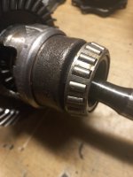
I used to break bearings off axle half shafts on rear wheel drive vehicles by smashing off the rollers/balls and their cages. doesn't sound as brutal as it might because they generally come off pretty easy. This leaves just the inner race on the shaft so you then use a small angle grinder with a cutting disk to grind a slot across the inner race. This introduces a stress concentration into the race which you can give a good whack to with something like a chizel - eye protection please - usually within one or two goodly hits the bearing race will crack along the groove so now it has no hold on the shaft and can be easily tapped/drifted off.
Edit. You don't need to grind the slot right through, even half way is usually enough.
Edit. You don't need to grind the slot right through, even half way is usually enough.
smart51
Established member
I've seen a diff dissasembly on YouTube but not done it myself. They unbolt the crown wheel and take out the differential gears, which allows you to remove the half shaft through the diff. You can then get a bearing puller on the race, but with nothing in the middle to push against. My first thought would be to bolt the diff to a piece of plywood in place of the crown wheel and put a block of something in the centre for the puller to push against.
If you are fitting new bearings, then Pugglt Auld Jock's suggestion should work fine. Just be sure you have the correct bearings to hand before starting.
Using a 2 or 3 leg puller in this situation, will only distort the bearing roller cage, rendering the bearing unfit for re-use. I note you're fitting new bearings anyway but you're unlikely to get sufficient purchase to pull the bearing, in my experience, the puller just ruins the cage and then slips off.
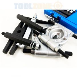
The correct way to remove diff. side bearings (and similar items) would be to use a bearing separator similar to this one :-
 ige.ie
In your situation, you can either place a steel bar across where the diff. side gears fit and use the puller ram/lead screw to push against this bar or attach a slide hammer in place of the puller ram/ lead screw and shock the bearing off.
If you don't happen to have such a bearing separator (and most dIY mechanics probably don't), you might possibly find a workshop so equipped to pull just the bearings for you?
Alternatively, (DIY mechanic's method)
Check if there are any recesses/cut-outs behind the perimeter of the bearing races into which a drift could be positioned in order to drive the bearing off.
If there are no recesses/cut-outs, you could try to drive a narrow blade between the bearing race and it's seating to begin opening a gap. In the past I've used, initially, a decorator's scraper or old kitchen knife to create an initial gap, followed by something a little wider e.g. old screwdriver or wood chisel. If trying this approach, I'd suggest using 2 scrapers or knife-blades - one held upright in a bench vice pressing against the junction of the bearing and housing, the other being driven downwards into the junction of the bearing and housing - this prevents the bearing from being "cocked" and jamming.
Using a 2 or 3 leg puller in this situation, will only distort the bearing roller cage, rendering the bearing unfit for re-use. I note you're fitting new bearings anyway but you're unlikely to get sufficient purchase to pull the bearing, in my experience, the puller just ruins the cage and then slips off.
The correct way to remove diff. side bearings (and similar items) would be to use a bearing separator similar to this one :-
Bearing Separator Set
For Removing Gears, Pulleys And Steering WheelsIncludes; 2 X Bearing Splitters, 1X H-Type Beam,1 X Lead Screw, 2 X 6"" Yoke Adaptor, 2 X 5"" Extension Screws ,1 X 4"" Screws With Male Threads, 1 X 5"" Extension Screws,1 X 4"" Extension Screws With Male Threads"
ige.ie
In your situation, you can either place a steel bar across where the diff. side gears fit and use the puller ram/lead screw to push against this bar or attach a slide hammer in place of the puller ram/ lead screw and shock the bearing off.
If you don't happen to have such a bearing separator (and most dIY mechanics probably don't), you might possibly find a workshop so equipped to pull just the bearings for you?
Alternatively, (DIY mechanic's method)
Check if there are any recesses/cut-outs behind the perimeter of the bearing races into which a drift could be positioned in order to drive the bearing off.
If there are no recesses/cut-outs, you could try to drive a narrow blade between the bearing race and it's seating to begin opening a gap. In the past I've used, initially, a decorator's scraper or old kitchen knife to create an initial gap, followed by something a little wider e.g. old screwdriver or wood chisel. If trying this approach, I'd suggest using 2 scrapers or knife-blades - one held upright in a bench vice pressing against the junction of the bearing and housing, the other being driven downwards into the junction of the bearing and housing - this prevents the bearing from being "cocked" and jamming.
Last edited:
OP
OP
jolly500
Member
Thank you all for your input.
I've got enough info there to make a plan, I'm sure.
Regards
Steve
I've got enough info there to make a plan, I'm sure.
Regards
Steve
Just used Puggit’s method. It was most satisfying.
The first bearing wouldn’t budge, but the puller did a good job of distorting the bearing cage. This made mullering it an easier job. Then worked very slowly & carefully with a small angle grinder. A cold chisel did the rest.
To my surprise, the second bearing came off with the puller
The first bearing wouldn’t budge, but the puller did a good job of distorting the bearing cage. This made mullering it an easier job. Then worked very slowly & carefully with a small angle grinder. A cold chisel did the rest.
To my surprise, the second bearing came off with the puller
OP
OP
jolly500
Member
Sorry gents, just another thought.
Would it be necessary to to reset the backlash on the diff after changing the bearings?
Regards
Steve
Would it be necessary to to reset the backlash on the diff after changing the bearings?
Regards
Steve
Omg, please tell me the answer is no!Sorry gents, just another thought.
Would it be necessary to to reset the backlash on the diff after changing the bearings?
Regards
Steve
And preload on the bearings ") .
.
When the diff bearings were removed were there any shims either side and if so did you keep them in order for each side so that you have a starting point.
Too many will make the diff bearings whine and seize due to too much preload on them, too few will give excessive backlash in the drive, etc. etc.
By the way did you disturb the pinion gear as well, as that is another that requires precise setting up if you don't want the car to sound like it is being attacked by a kamikaze dive bomber.
A fair bit of care and dial gauges, measurement of preload is etc. involved. Ideally some here on forum has a gearbox manual describing any specialist tools required and the settings etc.
If not it may be worth reading up about the principles of setting diffs in general.
There do seem to be a lot these days online. This is one though not Fiat, but basic principle the same:-

 www.yukongear.com
.When the diff bearings were removed were there any shims either side and if so did you keep them in order for each side so that you have a starting point.
Too many will make the diff bearings whine and seize due to too much preload on them, too few will give excessive backlash in the drive, etc. etc.
By the way did you disturb the pinion gear as well, as that is another that requires precise setting up if you don't want the car to sound like it is being attacked by a kamikaze dive bomber.
A fair bit of care and dial gauges, measurement of preload is etc. involved. Ideally some here on forum has a gearbox manual describing any specialist tools required and the settings etc.
If not it may be worth reading up about the principles of setting diffs in general.
There do seem to be a lot these days online. This is one though not Fiat, but basic principle the same:-
12 Tech Tips For Differential Assembly & Setup
This quick primer of tech tips is designed to be informational for less experienced installers and a refresher course for seasoned differential technicians.
www.yukongear.com
Really useful link. Thanks for that.
There was one shim on either side, and I have carefully stored them, so it’s a starting point.
I’ve also found a useful thread on the forum. There’s a YouTube link on the thread from several years ago, which has sadly expired.
There was one shim on either side, and I have carefully stored them, so it’s a starting point.
I’ve also found a useful thread on the forum. There’s a YouTube link on the thread from several years ago, which has sadly expired.
Oh yes! It all sounds a bit brutal and crude until you try it. In my earlier days I've spent literally hours trying to get inner races off of the likes of mini front hubs, Cortina half shafts, etc, etc. Smash the outer race, bearings and cage off, slit the inner race as mentioned, and as dapedza says above, taking care not to cause damage to the hub or shaft which could catastrophically weaken it - this applies particularly to half shafts. Then, with an old chizel and some eye protection (metal chips from the hardened race can become detached) give the slot a goodly whack and, CRACK! it'll split and loose it's hold on the hub/shaft. Job done and. if you're careful with the grinder, with no damage to the hub/shaft. It's strangely satisfying too!Just used Puggit’s method. It was most satisfying.
The first bearing wouldn’t budge, but the puller did a good job of distorting the bearing cage. This made mullering it an easier job. Then worked very slowly & carefully with a small angle grinder. A cold chisel did the rest.
To my surprise, the second bearing came off with the puller
Just a thought. Can you see the name of the manufacturer on the old bearing? could be a good staring point to source the same make of bearing? unlikely though that you'll just be able to reassemble it with the existing shims, could be a staring point though and worth a try, especially if the pinion hasn't been disturbed.Really useful link. Thanks for that.
There was one shim on either side, and I have carefully stored them, so it’s a starting point.
I’ve also found a useful thread on the forum. There’s a YouTube link on the thread from several years ago, which has sadly expired.
I've not done much of this although I did successfully rebuild one of my Imp transaxles which was not easy at all. Much more difficult than simply doing an old "A" series gearbox - we did a lot of layshafts in them I remember. I remember being taught in college how to use engineers blue to set up the teeth mesh pattern on an old Austin differential when I was being trained. But in the garage we just would fit an exchange diff or farm the rebuild out to our local gearbox shop. We did conventional front wheel drive stuff ourselves but they are simpler because there are no bevel gears to set up on the final drive,
I never did much with diffs in transaxles , but rwd pre crossflow Fords, Mazda B1600s, Lada and Moskvich etc. in the 1970/80s.Just a thought. Can you see the name of the manufacturer on the old bearing? could be a good staring point to source the same make of bearing? unlikely though that you'll just be able to reassemble it with the existing shims, could be a staring point though and worth a try, especially if the pinion hasn't been disturbed.
I've not done much of this although I did successfully rebuild one of my Imp transaxles which was not easy at all. Much more difficult than simply doing an old "A" series gearbox - we did a lot of layshafts in them I remember. I remember being taught in college how to use engineers blue to set up the teeth mesh pattern on an old Austin differential when I was being trained. But in the garage we just would fit an exchange diff or farm the rebuild out to our local gearbox shop. We did conventional front wheel drive stuff ourselves but they are simpler because there are no bevel gears to set up on the final drive,
I do have the Sykes Pickavant bearing separators similar to early photo in thread and have used them in my hydraulic press without bearing damage generally.
On basic ball bearings another trick once the race /cage has been removed is to fit a Benelli exhaust clamp around it tightly in the bearing groove and use a couple of tyre levers to prise the inner ring from the shaft, that usually worked quite well.
On rwd Fords and Ladas the half shaft bearing were removed much as you describe, smash off the outer on an anvil or squeezed up in the vice and clouted, then grind the inner as close to the shaft as you dare, followed by a couple of blows with a strong chisel to break the inner ring, you first had to do similar with the retaining collar, then press the new bearing into place, followed by heating the retaining collar and dropping it down the shaft to be cooled and then hold all into place. Careful not to damage as it also was where the inner half shaft seal worked.
I did buy a Sykes Pickavant ball bearing extractor kit where you created a space between the balls and inserted a pair of ball shape pieces with two flats on them, turned them through 90 degrees and when fitted to the extractor could pull bearings from blind holes etc. As I never used it much I sold it on, but it was a quality bit of kit.
Way back in the day, I helped out some friends by doing a couple of half shaft bearings by the kerbside at home over the weekend. I worked most Saturday mornings back in those days so the shafts were removed on the Saturday afternoon and had to wait 'till the Monday when I "smuggled" them into work and used the big hydraulic press on them. Not very convenient having the car at the kerbside up on stands for the duration and very obvious to the neighbours that It wasn't my car i was working on.
Far from being a problem when it became known I could "fix" cars several of the neighbours got me to do simple fixes on theirs in return for favours from them (plumbers, electricians etc) The whole thing worked out very well with us developing a sort of helpers cooperative where we all helped with our own areas of expertise without any cash changing hands.
Anything needing the press was always a problem due to the delay and people often needing their car to go to work on the Monday. By now I'd learned how to slit the bearing and crack it off which solved the removal problem but left the task of installing the new bearing (and locking collar on some) I was thinking about this one day when it occurred to me that a half shaft is actually a reasonably weighty object, could I use that to my advantage? Anyway, after quite a bit of experimenting i came up with this very simple idea:

So what is it? Nearest to camera is a length of thick wall pipe - it's actually off cuts of steam pipe welded together to give the length needed so it exceeds the length of the half shaft. Above it is a Marina half shaft which has had the end where the bearing and removable flange fit beaten into a flat. I use it for levering (doesn't bend even with a length of steam pipe used to lengthen the leverage) However here it's just to illustrate the length.
A friend faced off the ends in his lathe:

But the original length was not long enough so I cut it in half and welded another bit of off cut in the middle so I'd end up with the length needed. The idea is that you slip the new bearing onto the shaft then slip the whole shaft complete with the loosely fitted bearing inside the tube, like this (you'll have to imagine there's a bearing resting on the top of the tube end:

Then you lift the whole lot up about a foot or so from the floor, by gripping the tube, and let it drop vertically. The tube hits the floor and stops dead the inner race of the bearing is supported on the end of the tube and the half shaft is free to move inside the tube. It's a bit like a slide hammer in operation and what happens is that the bearing is slowly - takes a few drops to do - seated onto the shaft. The locking collar, with help from a bit of heat, is installed in the same way. Job done. And all at minimal cost. After I started breaking up the concrete floor in my garage I found a square of very thick steel plate which I then used to drop the tube on! If you're going to make one it's vitally important that the tube diameter is such that it supports the inner race of the bearing. If it bears on the outer race it'll ruin the bearing. Oh, and I can strongly recommend the steel plate on the floor. Not only does it stop you breaking up the concrete but it also stops the pipe more aggressively - the concrete "gives" slightly and reduces the impact - making installation quicker. You'll appreciate it's all about the impact. It's not going to work on a gravel driveway or your lawn!
Before the more observant of you start commenting, The BMC/BL men will be complaining I've chosen a particularly inappropriate half shaft because Marina half shafts had a removable flange which was keyed and tapered to the end of the shaft which you removed to do the bearing. In fact the bearing couldn't come off towards the diff because there was a thicker machined diameter which prevented this - you can just see this in board of the flattened end on mine - You'll remember, if you ever did one, that the flanges were often on so tight you could bend them if you simply tried to pull them off without heat.
Far from being a problem when it became known I could "fix" cars several of the neighbours got me to do simple fixes on theirs in return for favours from them (plumbers, electricians etc) The whole thing worked out very well with us developing a sort of helpers cooperative where we all helped with our own areas of expertise without any cash changing hands.
Anything needing the press was always a problem due to the delay and people often needing their car to go to work on the Monday. By now I'd learned how to slit the bearing and crack it off which solved the removal problem but left the task of installing the new bearing (and locking collar on some) I was thinking about this one day when it occurred to me that a half shaft is actually a reasonably weighty object, could I use that to my advantage? Anyway, after quite a bit of experimenting i came up with this very simple idea:
So what is it? Nearest to camera is a length of thick wall pipe - it's actually off cuts of steam pipe welded together to give the length needed so it exceeds the length of the half shaft. Above it is a Marina half shaft which has had the end where the bearing and removable flange fit beaten into a flat. I use it for levering (doesn't bend even with a length of steam pipe used to lengthen the leverage) However here it's just to illustrate the length.
A friend faced off the ends in his lathe:
But the original length was not long enough so I cut it in half and welded another bit of off cut in the middle so I'd end up with the length needed. The idea is that you slip the new bearing onto the shaft then slip the whole shaft complete with the loosely fitted bearing inside the tube, like this (you'll have to imagine there's a bearing resting on the top of the tube end:
Then you lift the whole lot up about a foot or so from the floor, by gripping the tube, and let it drop vertically. The tube hits the floor and stops dead the inner race of the bearing is supported on the end of the tube and the half shaft is free to move inside the tube. It's a bit like a slide hammer in operation and what happens is that the bearing is slowly - takes a few drops to do - seated onto the shaft. The locking collar, with help from a bit of heat, is installed in the same way. Job done. And all at minimal cost. After I started breaking up the concrete floor in my garage I found a square of very thick steel plate which I then used to drop the tube on! If you're going to make one it's vitally important that the tube diameter is such that it supports the inner race of the bearing. If it bears on the outer race it'll ruin the bearing. Oh, and I can strongly recommend the steel plate on the floor. Not only does it stop you breaking up the concrete but it also stops the pipe more aggressively - the concrete "gives" slightly and reduces the impact - making installation quicker. You'll appreciate it's all about the impact. It's not going to work on a gravel driveway or your lawn!
Before the more observant of you start commenting, The BMC/BL men will be complaining I've chosen a particularly inappropriate half shaft because Marina half shafts had a removable flange which was keyed and tapered to the end of the shaft which you removed to do the bearing. In fact the bearing couldn't come off towards the diff because there was a thicker machined diameter which prevented this - you can just see this in board of the flattened end on mine - You'll remember, if you ever did one, that the flanges were often on so tight you could bend them if you simply tried to pull them off without heat.
Hi, I have completed the backlash and bearing turning torque in line with the 'Haynes Manual' straightforward process, just take it slow and try setting things a few times before closing everything up.
Ian.
Ian.
Those and the Triumph ones even with the correct puller could be so tight it distorted the flange.Way back in the day, I helped out some friends by doing a couple of half shaft bearings by the kerbside at home over the weekend. I worked most Saturday mornings back in those days so the shafts were removed on the Saturday afternoon and had to wait 'till the Monday when I "smuggled" them into work and used the big hydraulic press on them. Not very convenient having the car at the kerbside up on stands for the duration and very obvious to the neighbours that It wasn't my car i was working on.
Far from being a problem when it became known I could "fix" cars several of the neighbours got me to do simple fixes on theirs in return for favours from them (plumbers, electricians etc) The whole thing worked out very well with us developing a sort of helpers cooperative where we all helped with our own areas of expertise without any cash changing hands.
Anything needing the press was always a problem due to the delay and people often needing their car to go to work on the Monday. By now I'd learned how to slit the bearing and crack it off which solved the removal problem but left the task of installing the new bearing (and locking collar on some) I was thinking about this one day when it occurred to me that a half shaft is actually a reasonably weighty object, could I use that to my advantage? Anyway, after quite a bit of experimenting i came up with this very simple idea:
View attachment 422552
So what is it? Nearest to camera is a length of thick wall pipe - it's actually off cuts of steam pipe welded together to give the length needed so it exceeds the length of the half shaft. Above it is a Marina half shaft which has had the end where the bearing and removable flange fit beaten into a flat. I use it for levering (doesn't bend even with a length of steam pipe used to lengthen the leverage) However here it's just to illustrate the length.
A friend faced off the ends in his lathe:
View attachment 422553
But the original length was not long enough so I cut it in half and welded another bit of off cut in the middle so I'd end up with the length needed. The idea is that you slip the new bearing onto the shaft then slip the whole shaft complete with the loosely fitted bearing inside the tube, like this (you'll have to imagine there's a bearing resting on the top of the tube end:
View attachment 422554
Then you lift the whole lot up about a foot or so from the floor, by gripping the tube, and let it drop vertically. The tube hits the floor and stops dead the inner race of the bearing is supported on the end of the tube and the half shaft is free to move inside the tube. It's a bit like a slide hammer in operation and what happens is that the bearing is slowly - takes a few drops to do - seated onto the shaft. The locking collar, with help from a bit of heat, is installed in the same way. Job done. And all at minimal cost. After I started breaking up the concrete floor in my garage I found a square of very thick steel plate which I then used to drop the tube on! If you're going to make one it's vitally important that the tube diameter is such that it supports the inner race of the bearing. If it bears on the outer race it'll ruin the bearing. Oh, and I can strongly recommend the steel plate on the floor. Not only does it stop you breaking up the concrete but it also stops the pipe more aggressively - the concrete "gives" slightly and reduces the impact - making installation quicker. You'll appreciate it's all about the impact. It's not going to work on a gravel driveway or your lawn!
Before the more observant of you start commenting, The BMC/BL men will be complaining I've chosen a particularly inappropriate half shaft because Marina half shafts had a removable flange which was keyed and tapered to the end of the shaft which you removed to do the bearing. In fact the bearing couldn't come off towards the diff because there was a thicker machined diameter which prevented this - you can just see this in board of the flattened end on mine - You'll remember, if you ever did one, that the flanges were often on so tight you could bend them if you simply tried to pull them off without heat.
My first press was a Harvey Frost ratchet and screw affair , the thread nut was a bit worn so wobbled but was fine for those half shaft bearings etc.
Over the years I have had several proper anvils one complete with all the blacksmith type tools,and very useful, I now just have a short section of RSJ which works for most stuff.
Years ago when stuck I used a heavy duty open ended spanner and a large copper mallet to drive bearings on to half shafts, being careful to keep to the inner race as you mentioned.
I am sure the ingenuity of some in the Third World could put as to shame with what they manage at the side of the road
.Some of the videos I've seen put us all to shame as far as inventiveness goes.I am sure the ingenuity of some in the Third World could put as to shame with what they manage at the side of the road
My brother in law, after a career as pilot with BEA went to Cyprus airways. You could continue to fly for them for longer than BEA would employ you. We spent many very happy summer holidays over there around Kyrenia until they had their war and later to the east of Larnaca where they were then based. I remember watching a chap who worked by the roadside doing panel repairs and paintwork. He was very busy every day as we drove past and the quality of finish he was achieving was better than I ever did in my lockup!
Thanks Ian, that’s encouraging to know. I’ve completed the box, so I’m now about to embark on the process. Just one stupid question: when doing the backlash, where exactly must I position the end of the DTI probe with respect to the crown gear? In other words, where must it make contact with the crown gear?Hi, I have completed the backlash and bearing turning torque in line with the 'Haynes Manual' straightforward process, just take it slow and try setting things a few times before closing everything up.
Ian.
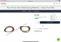
Also, I only have two inner drive shaft spring washers. I thought the setup would use four (two for each driveshaft)? Can’t see anything in the manuals.
Attachments
This is for back lash, though you also need to check for preload on the bearings via the spacers , bearing in mind what you do affects the depth of tooth engagement and so alters backlash etc.Thanks Ian, that’s encouraging to know. I’ve completed the box, so I’m now about to embark on the process. Just one stupid question: when doing the backlash, where exactly must I position the end of the DTI probe with respect to the crown gear? In other words, where must it make contact with the crown gear?
Also, I only have two inner drive shaft spring washers. I thought the setup would use four (two for each driveshaft)? Can’t see anything in the manuals.
Basically you are looking for a visible but small amount of backlash + a slight but noticeable amount of preload (enough to prevent gears moving in and out of good contact though not so much that it causes loading/overheating of the bearings), whilst at the same time the teeth should engage in the centre of the gear contact area.
Ideally you need the manufacturers original settings as a base line
.