Styling 595 mk1 to mk2 drl mods

Currently reading:
Styling 595 mk1 to mk2 drl mods

Nice scientific approach. I think this will help iwata a lot....:geek:

It's a good cure for insomnia if nothing else 😂

Even assuming he doesn't sit down and work through all the formulae and take a GCSE physics exam at the end, it helps to know what you're letting yourself in for though; after all he won't thank the poster of that thread if he cooks his headlight circuit.

To save a bit of reading (is that the definition of TLDR?) effectively if you were to short out the two terminals of a bulb you'd be putting a very low value resistor in parallel to the bulb, and the current may be enough to make something go 'bang'. Same if you use an actual resistor with way too low a value of course, it would create effectively a short circuit. Whereas if it's in serial and you foul it up the lowest resistance will be the value of the resistor + the resistance of the DRL, so worst case would be as if there's no resistor there at all.

Also, as per the formulae, assuming the controller is looking for a voltage drop rather than something else, it's much simpler to calculate the value of a serial resistor to use than a parallel resistor. And the heat generated in the resistor will (or should be) be less because the current will be flowing through both components equally, rather than the majority going through the resistor (serial - current remans constant across the components, parallel - current takes the path of least resistance).

As an aside, you normally use a serial resistor across the terminals to fool the airbag ecu in an airbag delete to emulate the voltage drop across the airbag (as in the elusive little orange plug used when fitting Sabelt seats), though you didn't hear that from me 🤫
 
Last edited:
Thank you guys for your help, ive ordered 100ohm resistors, hopefully getting it in two days.

So when i swapped the wires so ring as drl, headlights on would switch ring off, the single 21w bulb would go on and stay on when doing one side only, no resistor wired in. both sides would switch off straight away as noted earlier in this thread. maybe doing one side shows good results.

Another thing is when wired in correctly, ring is on when headlights are on, connecting diagnostic software i can turn on day running light also, it will stay on until i switch off via diagnostic, could it be a coding instance?
 
I know on my 2015 Abarth there's an option in the dashboard menu for turning the DRLs on or off (I think they're off by default) so worth checking that too...

Sounds like there's some quirk in the wiring though if one works fine and both together don't, suggests they may be wired in parallel themselves (which would give the resistance of just one DRL if the other's disconnected) so if the 100 ohm doesn't work could be all you need to do is find out the wattage of the DRLs, divide 144 by that and then you'll have the approx value of the resistors you need to wire in serial to the DRLs on each side.

(if anyone can be bothered with the maths, v=ir, and w=vi. Therefore if v=12 approx, w=12i and i=12/r giving w=144/r so 144/w=resistance you need approx, assuming my maths hasn't gone wonky at the end of the day)


Edit: oops, I did miss a bit; forgot the impedance of the existing lights vs the DRLs, so my calculation above won't work.

Edit2: Did some more reading around it (I'm intrigued now) and it looks like the parallel mod can work, but it's a bit odd how you get it to function, and the OP 'doesn't recommend' it:
 
Last edited:
Another thing is when wired in correctly, ring is on when headlights are on, connecting diagnostic software i can turn on day running light also, it will stay on until i switch off via diagnostic, could it be a coding instance?

Yes this is the correct function in mk2 models. This is all light modes in my car:


And this is how to activate and deactivate DRL: https://www.manua.ls/fiat/500-2011/manual?p=21

Edit2: Did some more reading around it (I'm intrigued now) and it looks like the parallel mod can work, but it's a bit odd how you get it to function, and the OP 'doesn't recommend' it:

Take care with is link. This is for US-Models. They have a different cable assignement as the indicator is located also in the lower lamp and no high-beam. Cable colours are different, too.
 
Take care with is link. This is for US-Models. They have a different cable assignement as the indicator is located also in the lower lamp and no high-beam. Cable colours are different, too.

But judging by the age, the form of the article and the suggestion of using a resistor in parallel as a tie-down, I suspect this 2011 US article may have been what the German article was based on. Trouble is without a wiring diagram and conclusive knowledge how the later DRLs work and are set up (I have seem some suggestions they're directly controlled by the CAN bus but that seems highly unlikely) it is really just witchcraft and guesswork. For example it appears the original poster in the German thread just installed the LED lights with no resistors and hit no issues whatsoever, so there must be something more 'interesting' going on, maybe based on the year the car was manufactured. Also the suggestion in the thread that 2x 5 ohm resistors in parallel will work the same as 1x 10 ohm is incorrect.

When I did the calculations with approximate power values for the LEDs vs the standard bulbs it appears I'm wrong and trying to do it just with a series resistor won't work (though there are plenty of aftermarket LED kits for headlights, etc which do just use a series resistor), so we can count that out but using a parallel resistor is risky. Maybe the solution is really in software, and turning off the check for correct DRL voltage (or whatever) is the right way to go, in much the same way as removing the rear O2 sensor and turning off the check / alert in software is the right thing to do if you perform a cat delete on many cars.

Maybe it will work for the OP and maybe the LEDs will work fine with 100 ohm in parallel, but I suspect there may be more trial and (t)error to come yet before we can say for definite "yes you can fit later LED DRLs to pre-facelift cars"

Fascinating nonetheless, if I wasn't already occupied with making other modifications to my car (I also prefer the less aggressive pre-fl bumper so want to stick to that) I'd be tempted to get out all the multimeters, hunt down a facelift wiring diagram and have a play myself because I like this kind of problem. But I'm definitely waiting with baited breath to find out if it all works :)
 
Last edited:
I think guessing is the one thing, having experience is the other.

I run LEDs for the DRL in my 595. 20200817_105119.jpg

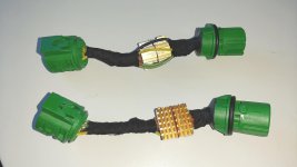
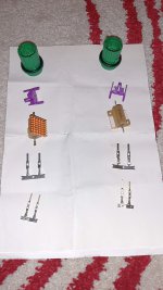
There fore I created two adapters were the resistor is installed in parallel.

stecker_fertig.jpg kit.jpg connector_text.jpg

The reason for the adapters is, that the car is still in warranty and I didn´t want to do this to the original wiring harness. So I can remove everything without any remains. In this case I used 15Ohm / 25W resistor on each side and this works well. No message in my car. I did the same to the rear fog lamp, as it is controlled, too.

T15_LED_rot_m_Lampetraeger_2.jpg T15_LED_rot_m_Lampetraeger_3.jpg

Interestingly, the reverse light, the low and the high beam are not controlled.

But when I understand the OP correctly, the DRL is not the problem, only the LED-ring, but this is more the position light. And I think there is a difference in the operation strategy.

In the mk1 models, if you have ignition on and no low beam on, then the DRL is aktive, this means the 21W filament is glowing. When the low beam is activated, then the DRL is switched off and the position light, the 5W filament is aktive.

In the mk2 models it´s a little bit different. The LED-Ring is allways active, independent if only the ignition is on and the low beam off. If ignition on, then the additionally the DRL 21W blub is glowing, the low beam is activated, the DRL bulb is switched off, but the LED ring stays on.

This means to have this behaviour also in a mk1 model, little bit more is necessary.
 
Ah, I wondered if there might be version-related problems, and by the looks of it the OP in the German thread is running a version (is the German OP's S1 or 3?) which doesn't need an adaptor at all. So I'm guessing for the OP in this thread's model a load resistor for the position light will be necessary to fool the BCU into thinking the old light is present, and a separate switched +12v feed run to the LED ring to make it behave the same.

So in your adaptors the resistor is wired between headlight gnd and the DRL wire? Must admit I wouldn't fancy that idea myself, but if it doesn't cause the wiring (or resistor) to get excessively hot and has been running for some time with no issues I guess you've cracked it, at least for your version. Is yours a pre-facelift S3 or facelift S4? (think I've got the versioning correct - S1 is the pre-2014 one with the analogue speedo, S2 didn't exist, 2014-2016 S3 has the colour TFT speedo and S4 is the post-2016 facelift with the more modern bumper and LED ring)

Edit: Ah, if still under warranty presumably a S4
 
Last edited:
So if my understanding is right, we're talking about two separate problems, one is getting the LED ring to work, the other is a conversion to use LED lights in place of the standard bulbs, a well-trodden path on many cars (though one which I wouldn't attempt personally, especially as aftermarket LED conversions are now an MOT fail in the UK).

If we assume a standard incandescent bulb will still work fine for the DRL we can leave the LED conversion alone at the moment (until the OP is ready to try it) and concentrate on the LED ring problem. If the existing position light no longer exists in it's current form, first stage will be fooling the BCU into thinking it's still there. That will need a resistor between the position light feed and ground; that will need to be more than 25 ohm (I can go through the calculation if anyone's interested) to avoid any wiring damage. Anything up to about 3.3k works ok in most systems as a 'dummy load', so a larger resistor would be a better idea since it'll cause less battery drain / heat to be generated in the resistor; might be a matter of trying different resistors to see what the maximum size the BCU will accept before logging a fault, but personally I'd start around 3k.

Once the error light is gone we can then look at the feed for the LED position lights. From your description above @Olliver it sounds like the LED ring runs constantly as long as the ignition is switched on, so all it will need is a switched +12v power supply, which could be picked up relatively easily from the fuse box. Things get more complicated if the LED ring turns off when the dipped or main beam is on, but maybe that could be dealt with by a relay as the simplest possible fix; we can look into that later maybe
 
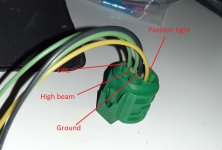
The Ground is common for high beam, LED-ring and DRL.

20210211_090228_copy_1280x720 (1).jpg

Mine is a 2020 model.

By the way, has somebody here the Haynes Manual for the 500? I´m interested in the wiring diagramm, too...
 
Last edited:
Update, so i got 2 x 100ohm resistors, wired this to position lead, the LED- ring, in parallel, still have dashboard warning light showing fault.
The light fault showing always goes on when the LED-ring is on.
 
This is is really strange, because normally the two 56 Ohm resistors are enough - even without any other load installed - that the dash will throw no error. Can you supply some pictures how you realized the Installation of the resistors? Did you install them in the lamp (quite unlikely due to the fact that there is not enough space), or in the wiring harness to the lamp??
 
This is is really strange, because normally the two 56 Ohm resistors are enough - even without any other load installed - that the dash will throw no error. Can you supply some pictures how you realized the Installation of the resistors? Did you install them in the lamp (quite unlikely due to the fact that there is not enough space), or in the wiring harness to the lamp??

I think @iwata may still be trying to get the LED rim lights working as a DRL using the original position light wiring, which is where I think we got our wires crossed, in all senses of the word :) Though hopefully he can provide a bit more insight with some pics...

@iwata - If you can, try and draw out the wiring circuit as best you understand it too, including how you've wired the resistors.
 
Fellas, Just to confirm wires for the DRL/side light is in original position. When car starts the single 21w bulb is on, ring is off, no faults on dash, when headlights is switched on, LED-ring goes on, 21w bulb goes off. fault is on dash.
When the wires was crossed, so LED-ring is first on when car started, fault showed up immediately.
I know that using a fused, ignition on wire would get the LED on always but like to resolve this first before doing another way.
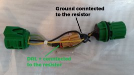
So how i wired it is one end to ground and other end to position light, yellow/ black wire, done on the wiring loom,
here is the link to the resistor i ordered, any good you reckon?
both resistors are warm/hot to touch when on, ill get some pictures up asap.
 
Sounds like from what @Olliver said the LED ring operates in an entirely different way to the position light on the facelift cars, so even if you do get it working in original form it might look kindof wrong:

In the mk1 models, if you have ignition on and no low beam on, then the DRL is aktive, this means the 21W filament is glowing. When the low beam is activated, then the DRL is switched off and the position light, the 5W filament is aktive.

In the mk2 models it´s a little bit different. The LED-Ring is allways active, independent if only the ignition is on and the low beam off. If ignition on, then the additionally the DRL 21W blub is glowing, the low beam is activated, the DRL bulb is switched off, but the LED ring stays on.

This means to have this behaviour also in a mk1 model, little bit more is necessary.

Sounds like your 21W bulb is acting as it should however with the wiring as it is so that side of things should be fine. I'd have thought the resistor wattage (plus heatsink) would be sufficient and sounds like you have indeed got it wired in parallel, but not sure about the resistance (ohms).

If you have a multimeter and still have an original light assembly handy, measure the voltage across the original 5W bulb when connected to 12v (there should be a voltage drop of some sort which the multimeter can measure, in theory should be 12v), then put the multimeter on amps, put the power feed wire on one of the multimeter's probes and put the other one on the bulb terminal so you can measure the current drawn. Repeat with your new setup complete with the parallel resistor and repeat once again with LED ring and the parallel resistor removed. Put the values on here, complete with your wiring diagram for the position light (just to confirm things are wired up right).

Personally I wouldn't try and get the appropriate voltage drop using a parallel resistor, but doesn't sound like anything's in danger of going 'bang' so it might work if we can get the resistance values right (ohms = voltage / current, so if we know voltage and current we should know what the correct resistance should be, and whether the 100 ohm is massively out).
 
Sorry guys, been very busy, not had a minute but i found some, plan on using the multimeter over the weekend to test values.
 
Back
Top