Styling 595 mk1 to mk2 drl mods

Currently reading:
Styling 595 mk1 to mk2 drl mods

iwata

New member
Joined
Dec 31, 2021
Messages
17
Points
2
Location
enfield
Hello to allđź‘‹

I have a series 1 595 that's 2016 registered. bought with damage to the front so decided to get facelift bumpers and lights for front and rear.
Rear lights wired together with rear bumper no problem.
Front headlights straight forward in bolt on and plugin.
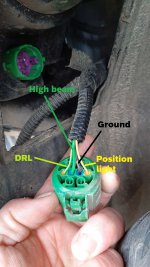
Problem I'm having is the day running lights working as intended. again it plugs in no problem however the led on new drls work only when headlights are on,
the incandesant dr lights are on when headlights are off. it should be the other way round. i suspect it maybe a relay causing this. Also dash warning light is showing a fault
Any guidance to resolve this, has anyone done this mod?
 
Nope, but chances are you'll just need to swap the wires over. However, have you checked the condition of the bumper mounts and chassis legs out properly? They are a pretty important part of the car's crash safety but seem to be more easily damaged in a front end impact than the bumper.

Mine was a Cat N with what appeared to be very light damage (wing was damaged but front bumper was reusable except for bottom grille and a couple of small cracks in the top) but when I started to dig further I discovered damage to the bumper mount which had bent the front part of the chassis leg, and I ended up having to weld in a new chassis leg section!
 
Mine is cat s, damage sent it out of alignment towards the n/s by about 10 -20cm, straightened by jigwork no problem.
Wires have been swapped over as well, i guess resistors will be needed as the incandescent bulbs in the drl goes on when headlights are on , then goes off in 2 seconds.
 
Ah, good stuff :) Just wanted to make sure you were aware of possible chassis leg damage but sounds like you're on top of it (y)

As for the wiring, it's a bit of a tricky one because the phase 4 / facelift doesn't seem to have any online factory service manuals or wiring diagrams, which makes any wiring work more guesswork unless someone out there's successfully done it before and hasn't spoken up yet. So you might end up having to directly compare the wiring on another facelift vehicle to yours to get some clues.

I wouldn't have thought the lights are directly CAN bus controlled on later cars so hopefully it will be something simple, though to me it still sounds like the wires are 'upside down' so to speak even if the loom has been swapped so might be worth investigating the voltages / current drawn and trying a wire swap, unless you swapped the control unit too.

If all else fails can you fit the pre-facelift main beams / DRLs to get you going?
 
For the LED-position light (the ring) you will need load resistors, as their current comsumption is much lower compared to the 5W the filament has, and so it will be diagnosed as not working. For the DRL it is the same as before, it´s a conventional 21W bulb (Mk.2 only one filament).
Attached the pin assignment (left side).
 

Attachments

  • pinning.jpg
    pinning.jpg
    222.1 KB · Views: 84
Thank you Oliver, would you know what resistor wattage needed?
With the wiring, i swapped the 2 outer wires over so the ring is on when lights are off. i noticed on others the ring light is on all the time.
When h/light are switched on the mk2 single filament light would go on briefly then goes off.
 
So the question for me is first, will you keep the wrong wire assignment with the switched cables or not?

In case you correct it, as it is designed for the mk2 models you need for the ring a load resistor with 56 Ohm and 5Watt connected to ground. The singlefilament will then simply work. The reason why it goes briefly off is, that the control module expects a 5W bulb, but you connected the 21W buld, so it switches off to avoid overheating.

In case you keep your wrong pin assignment, you need for the ring a load resistor with 10 Ohm and 25W (will become hot!), and you need to replace the the single filament bulb by one with only 5W (perhaps you take a mk1 dual filament bulb and bend the contacts that way that only the 5W filament is working) or you can try a LED (e.g. https://www.ebay.co.uk/itm/255062582832 ) as they normally have around 3-4W and this could be enough.
 
This post contains affiliate links which may earn a commission at no additional cost to you.
So the question for me is first, will you keep the wrong wire assignment with the switched cables or not?

In case you correct it, as it is designed for the mk2 models you need for the ring a load resistor with 56 Ohm and 5Watt connected to ground. The singlefilament will then simply work. The reason why it goes briefly off is, that the control module expects a 5W bulb, but you connected the 21W buld, so it switches off to avoid overheating.

In case you keep your wrong pin assignment, you need for the ring a load resistor with 10 Ohm and 25W (will become hot!), and you need to replace the the single filament bulb by one with only 5W (perhaps you take a mk1 dual filament bulb and bend the contacts that way that only the 5W filament is working) or you can try a LED (e.g. https://www.ebay.co.uk/itm/255062582832 ) as they normally have around 3-4W and this could be enough.

Thought it sounded like the wires were the wrong way round, but I'm not sure if the OP has swapped the wires already.

This would be a good subject for a 'howto' if you don't mind writing one - good pre-fl front bumpers are getting rarer (and more expensive) now so I suspect this sort of swap will become more common as time goes on.
 
This post contains affiliate links which may earn a commission at no additional cost to you.
Thank you Oliver, i will give it try, the wiring will be returned as original as i dont like the idea of resistors getting hot like that.
 
Last edited:
This post contains affiliate links which may earn a commission at no additional cost to you.
uk ebay doesn't have them with values needed like the ones linked. the electrical stores i tried have near values like 50ohm or 60ohms, when i do find its 10w,cant seem to find one that have the right values and body which looks the same as the first one you linked.
As with the link attached, none have the body, still searching but very frustrating.

https://www.mouser.co.uk/c/passive-... W&resistance=56 Ohms&termination style=Axial
 
okay, i was told the same by a guy that can hopefully help me out.
 
Got the resistors, 10w 56ohms. wired them in, it still shows up as faulty on the ring side, no matter which way its wired up.
wiring back as it was originally.
 
Has anyone been able to find a wiring diagram (or full service manual) for the facelift / version 4 yet on the German forum?

This sort of thing is normally quite straightforward once the wiring and input / outputs from the control module have been checked and altered as appropriate (I've done similar things a few times on Subarus) but it really is 'wild west' territory without that information. To me tying a +12v power feed to ground with a resistor sounds risky (not surprising the resistor gets hot!), might be better to measure the impedance of the standard bulb and the LED DRL, take one value away from the other and wire a resistor with the value of the difference in series with the LEDs (i.e. actually wire it into the power feed wire) rather than trying to tie a power feed direct to ground, assuming the error is caused by the control module not detecting the voltage drop it expects.
 
Last edited:
No I don´t know of wiring diagram, but I have posted the cable assignment above. You have same problems with your theory. Measuring the impedance of a bulb will give you the resistance when the filament is cold and this is much lower than in operation. And the impedance of a LED you simply cant measure because it is no ohmic load. In both cases you can only measure current and voltage and then calculate the electric power. And installing the resistor in series will not increase the load, it will further reduced. Why is it risky to install such a resistor to the ground? The mk1 bulb is also connected to the ground. That it will become hot is clear, did you ever touched a glow bulb, that quite hot, too...
 
Just general electrical / electronic good practice, it's generally considered a bad idea to connect a line which could be carrying high current direct to ground due to reducing the life of the resistor, and the risk if the wrong resistor's used (or the wire is shorted) that it'll kill something further up the power supply chain. Tie-down resistors are fine for signal lines, but this is a line which could in theory carry a lot of current.

Impedance will change for the bulb but it'll be fairly constant, so assuming the control unit is detecting a specific voltage drop to say whether the bulb is present or not, all you need to do is emulate that voltage drop. Best way would be to measure the voltage drop across both components given a constant current (or alternatively measure the current too with an inline ammeter) and then you can calculate the resistance (and thus difference / value of resistor needed) using the formula v=ir (where v is voltage, r is resistance and i is current) but as a rule of thumb measuring the resistance across both components when not in use should be close enough.

LEDs have an 'effective resistance' based on the voltage drop, here's an example of how to find that

Edit: and here's a guide to the normal use of pull-up / tie down resistors for controlling signal values

And another one for how dropping voltage with serial / parallel resistors works
 
Last edited:
Back
Top