So it could be a faulty new water sensor if it's a combined water/Fuel temperature sensor.They broke the water sensor when the changed my fuel filter - I had to go away with the van so I came back later to get the new water sensor mounted. After that the engine light was still on and this time the code was P0180, indicating problems with the fuel temperature sensor...


You are using an out of date browser. It may not display this or other websites correctly.
You should upgrade or use an alternative browser.
You should upgrade or use an alternative browser.
Technical 2014 Ducato - Fuel temperature sensor location
- Thread starter gonbes
- Start date
Currently reading:
Technical 2014 Ducato - Fuel temperature sensor location
How many wires are going to the water sensor?They broke the water sensor when the changed my fuel filter - I had to go away with the van so I came back later to get the new water sensor mounted. After that the engine light was still on and this time the code was P0180, indicating problems with the fuel temperature sensor...
Five as far as I can seeHow many wires are going to the water sensor?
Then I suspect it could be a combined water and temperature sensor. Three wires for the water sensor, The Positive , Negative and Signal wires and two for the temperature sensor.Five as far as I can see
I just got a link to a useful PDF: https://campervanineurope.wordpress...6/09/fiat-ducato-1st_x250_training-manual.pdf It seems quite likely that it can be right for my van.
In that case page 51 shows the fuel temperature sensor to be located at the high pressure fuel pump.

To dark & cold to check now but I hope to have the time tomorrow
In that case page 51 shows the fuel temperature sensor to be located at the high pressure fuel pump.
To dark & cold to check now but I hope to have the time tomorrow
I just got a link to a useful PDF: https://campervanineurope.wordpress...6/09/fiat-ducato-1st_x250_training-manual.pdf It seems quite likely that it can be right for my van.
In that case page 51 shows the fuel temperature sensor to be located at the high pressure fuel pump.
View attachment 454429
To dark & cold to check now but I hope to have the time tomorrow
That's for the 2.2 ford engine
The 2.3 fiat engine is pages 88 on
I should have known it was to good to be trueThat's for the 2.2 ford engine
The 2.3 fiat engine is pages 88 on

For the 2.3 engine I can't even see that the fuel temperature sensor is mentioned in the whole document - Strange...
I should have known it was to good to be true
For the 2.3 engine I can't even see that the fuel temperature sensor is mentioned in the whole document - Strange...
The fault coincided with broken sensor in bottom of fuel filter being replaced ............
Yes that’s right.The fault coincided with broken sensor in bottom of fuel filter being replaced ............
I’ve now got another PDF sent to me ( eLearn for 2,3 Euro 4/5) and marked text on page 3 + schematics following pictures suggests, if I understand things right, that the idea of a combined sensor for water & temp in the bottom of the filter would be right. The picture on p7 absolutely suggests this. - Just as suggested by you guys already

Next step shall in that case be to Google up some info to, hopefully, make it possible to test the sensor with a multimeter. It would be nice not to have to demont it, and get diesel everywhere…
If it then shows to be faulty the garage will have to fixx it for free
- I don’t want to pay them for localising the problem though, that sort of work often tends to get expensive (my experience at least).
Attachments
Vh and nh are the colour codes in italian for the wires that connect to the temp sensor part . Find out what colours vh and nh represent.
Disconnect the connector before probing the sensor , if you don't you will get incorrect readings .
Disconnect the connector before probing the sensor , if you don't you will get incorrect readings .
Last edited:
Any help? Euro5 K101 FUEL TEMPERATURE AND WATER IN FUEL FILTER SENSOR
Last edited:
https://www.fiatforum.com/threads/wiring-colour-codes.474703/ - According to this thread that would, if I understand things right, be :Vh and nh are the colour codes in italian for the wires that connect to the temp sensor part . Find out what colours vh and nh represent.
Disconnect the connector before probing the sensor , if you don't you will get incorrect readings .
NH = Black/Grey and VH = Green/Grey
Right now I might then only be left with the question how to probe the sensor (with a multimeter) and what readings would be right…
Disconnect wiring plug as previously mentioned. Resistance setting on multi meter (probably 2k ohm range)Probe the pins on sensor plug for temp sensor .
If sensor shows infinite resistance(open circuit) sensor is definitely faulty .
If sensor shows infinite resistance(open circuit) sensor is definitely faulty .
This chart is the temperature / resistance characteristics for K081 which I was the sensor on the 2.2 engine that was fitted to the high pressure pump. I wonder is the filter fitted sensors are similar?
I am not sure of the pin out for the temperature sensor. It would be interesting to do some resistance tests and work out the water and fuel temperature connections with reference to the K101 sensor details I posted on Wednesday. Anyone care to have a stab at what pins the temperature sensor is connected to ?
I am surprised that I cannot find a schematic wiring diagram of the sensor internal circuit on the web. The Sensor's that are for sale on the web only refer to it as a water in fuel sensor and the cost seems to vary from £10/20 up to £70 or so
Attachments

Last edited:
They are numbered 1 - 5 as per the plug pin out diagram in my link to K101Yes temp sensors usually similar resistance/temp....so op should select 5k or 10k range on their multi meter.
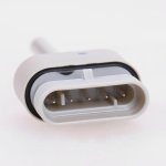
Pins on sensor are 1 an 2 for temp sensor......but I don't know which edge the numbering starts
Great so the op needs to translate that to the socket on the sensor and cross check using the wire colours .They are numbered 1 - 5 as per the plug pin out diagram in my link to K101
Do you know if the pin numbering convention is viewed from rear of plug or front of plug?
Cheers J
Sorry I was not correct. The K101 diagram is the sensor socket itself. The plug can only be inserted one way round should be no problem to identify pin 1Great so the op needs to translate that to the socket on the sensor and cross check using the wire colours .
Do you know if the pin numbering convention is viewed from rear of plug or front of plug?
Cheers J
Attachments
Similar threads
- Replies
- 2
- Views
- 204