Technical 1978 124 Project

Currently reading:
Technical 1978 124 Project

I am running a mechanical fuel pump with twin 40 IDF’s and it works great. The only downside is a long crank to prime the fuel system if you park the car up for a few weeks.
Electric fuel pumps can be more tricky and might need a pressure regulator and a shut off switch. Too much fuel pressure can flood the carb and may result in petrol gettinh into the sump and contaminating the engine oil
Then there is the cost! Mech fuel pumps can be £30-40. Elec pump £70-140, Pressure regulator and £70 Elec pumps also need a filter in the suction side of the pump (stated by pump manufacturer)
Also - any good way to test a mech fuel pump out of the car? I'd prefer to ensure its viability before doing all the reassembly / installation. I have had it out and put a line on the inlet to a small unit of gasoline, and then actuated the pump by hand. Mixed results, but I'm not sure if it's due to my neanderthal-like testing methods.... Notably, I felt some air blowing out of the tiny adjustment screw port (???)....
 
Again hopefully someone can give you better advice than me, but, when I installed my new one 2 months ago, I used an oem pump made in Italy part, still in the box, not sure how old it was, but I had it 5 years on the shelf.
Out of the box and activating the arm it was obvious from the "wooshing" sound it was working, and I tested it by putting my finger on the inlet pipe and it was easy to feel the vacume.
Comparing the vacume with my finger I also noticed it had "more" power than the the removed original....I know your on a budget but I would consider a new one due to the relative inexpensive cost, and the fact it's a pain in the butt to get to if your motors in the car with the intake on
On that note I would add I found it easier to attach the inlet, and outlet soft lines to the pump first, than mounting it to the block rather than trying to do it the opposite way...
Thanks Slotman - I did go ahead and install it, and did price some new ones. I think I’ll find some $$ for a new one as - and I agree - replacing when the motor is in will be a pain.
 
Again hopefully someone can give you better advice than me, but, when I installed my new one 2 months ago, I used an oem pump made in Italy part, still in the box, not sure how old it was, but I had it 5 years on the shelf.
Out of the box and activating the arm it was obvious from the "wooshing" sound it was working, and I tested it by putting my finger on the inlet pipe and it was easy to feel the vacume.
Comparing the vacume with my finger I also noticed it had "more" power than the the removed original....I know your on a budget but I would consider a new one due to the relative inexpensive cost, and the fact it's a pain in the butt to get to if your motors in the car with the intake on
On that note I would add I found it easier to attach the inlet, and outlet soft lines to the pump first, than mounting it to the block rather than trying to do it the opposite way...
I think what you have suggested is as good as its going to get. There are no specs for the fuel pump for carb engines afaik so whilst you could measure things there is nothing to compare to!
 
The method that @Slotman has suggested is the usual way of checking if a fuel pump is working.

On mechanical fuel pumps that have been left unused for a long time, I would dribble some fuel into the inlet and outlet pipes and let it soak in, to try to 'lubricate' the valves before testing it. The valves are usually little fibre discs that are helped to close by very soft springs in their housings - these discs and springs can dry out or become gummed up with the same sediment from evaporated fuel that can clog filter screens etc. in the fuel system.

Another test that can be performed on mechanical fuel pumps is to measure the volume of fuel pumped in a set period of time e.g. 1 litre in 1 minute of engine idling, but, of course, this requires an engine that can be run... As long as the pump can pump sufficient fuel to meet the engine's demands and can develop enough pressure to lift the fuel up to the carb reliably, it should be fine in use. Any surplus fuel will be returned to the tank which helps with fuel cooling etc. Too much pressure being generated can overwhelm the carb float valve and cause problems such as 'flooding' of the engine.

As @Twink80 has said, fuel pump test pressures are not usually stated in 'shop manuals.

However, I did find fuel pump pressures given in an old Autodata Technical Data Manual - and while it didn't give the mechanical fuel pump pressure for the 124 Spider, it did give this pressure for the Fiat 132 1600, 1800 and 2000 engines - the 132, 1800 used the 1756cc engine and had a 34DMS carb, the 132, 2000 used the 1995cc engine and had a 34ADF carb - in both cases the fuel pump pressure is given as 0.28 - 0.32 bar (4.06 - 4.64 psi).
In various carb books I've read, the fuel pump pressure requirement is usually recommended to be approx. 2.5 - 4 psi.

There are gauges available that can measure both this low pressure at the outlet port and also the vacuum at the inlet port but they're not usually needed.
(and I'm certainly not trying to entice anyone to spend money....)
 
Last edited:
----------------------------------------I felt some air blowing out of the tiny adjustment screw port (???)....
I haven't seen any 'adjustment screw port' on any mechanical fuel pumps that I've encountered?

Some pumps have a double 'rubber type' diaphragm situated between the upper and lower parts of the pump, this double diaphragm is separated by a plastic ring, this ring often has one or 2 holes on its outside face designed to indicate if one of the 2 diaphragms have failed - if fuel leaks from this hole then the upper diaphragm has failed, if engine oil leaks out from this hole the lower diaphragm has failed. Perhaps this hole/s is where you're feeling air exiting?
 
IMG_8342.jpeg

I promise that if this thing runs, you all will get credit. And if it blows up I’ll take the blame!
Opted for a new mechanical fuel pump and I’m glad I did, just based on the ‘in my hands’ comparison. Some other new bits and I’m off to the store to find some new nuts / and one missing bolt for the intake manifold.
Good news: I spun the motor by hand and it didn’t do anything weird!
More soon.
 
Update: Question about timing… I *think* I may have confused TDC (with all timing marks at ‘home’ as illustrated in my video) with what Haynes is asking for (see pic).
 

Attachments

  • image.jpg
    image.jpg
    2.4 MB · Views: 1
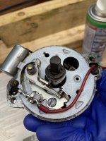
Bonus question: I think my distributor is no good, based on the metal conductor that fell out when I pulled the rotating button off. I think that button needs conductivity with continuous metal from the point of contact with the wire terminals down to the distributor post…
 

Attachments

  • IMG_8345.jpeg
    IMG_8345.jpeg
    1.2 MB · Views: 3
  • IMG_8344.jpeg
    IMG_8344.jpeg
    1.3 MB · Views: 3
Just wanted to mention, if you change the pilot bearing it needs to be done before the flywheel....:)
“Pilot bearing” is this the bearing at the back end of the crankshaft? (Sorry not fluent yet). If so I have changed it already.

The other bearing I am bearing (can’t help it) in mind is the (what I used to know as) “throw out” bearing for the clutch. That I have not yet investigated…
 
Re: Valve timing versus distributor timing....
@smahaley, the valve timing is correct in your video!
Where the Haynes manual is confusing you is that having given instructions on setting the valve timing earlier in the chapter they are now giving instructions on how to time the distributor using No. 1 cylinder as is done on most engines.

However, as I have explained in several previous posts to various members :rolleyes: on the Fiat twin cam engine, when the valve timing has been set (i.e. all the relevant marks correctly aligned), the distributor should be inserted and set so that the rotor arm is pointing to the distributor segment for No. 4 cylinder - i.e. this engine is timed on No. 4 cylinder not the more usual No. 1 cyl. If you check the cam lobe positions/orientations when the valve timing marks are correctly set (as in your video) you'll find the the cam lobes on No. 4 cylinder are pointing away from the valves i.e. both valves are fully closed and the piston is at tdc at the end of it's compression stroke and about to fire.

What Haynes have done instead, is given instructions on how to time the engine to No. 1 cyl. - in order to do the distributor timing this way, it is necessary to turn the crank one complete turn from when the valve timing marks are correctly aligned, this will turn both cams by 1/2 turn, resulting in the cam lobes now pointing away from the valves on No.1 cyl. and then the distributor can be inserted/set so that the rotor arm is pointing at distributor cap segment for No 1 cylinder. This is what paragraph 58 from the Haynes manual you posted is instructing you to do.

Now that I've probably confused you even more, I'll try to give you the simple solution...

Align your valve timing marks (as in your video), insert the distributor so that the rotor arm is pointing at the distributor segment for No. 4 cylinder.


A couple of others tips:-
Don't confuse yourself by turning the crank to the ignition timing position (10* btdc), just insert the distributor with the crank at tdc, then turn the crank backwards to the 10* btdc timing mark and then turn the distributor approx. 5* counter-clockwise (the distributor turns at 1/2 crank speed) so the points are just opening - this should give you near-enough correct ignition timing to start the engine.

As regards inserting the distributor body into the cam housing - as it's gear driven, it can be installed in various positions - I'd suggest marking the distributor body to show where the rotor arm should be pointing when it's positioned at the segment of the distributor cap for No. 4 cylinder (look at the distributor cap for cyl. numbers to find no. 4 and trial fit the distributor cap (a locating peg means it can only be fitted in one position) on the distributor body to determine where to make your mark. Hold the rotor shaft in this position relative to the distributor body as you insert the distributor. You also need to decide how to position the distributor body so that the plug leads are pointing in a suitable direction. The shape of the drive-gear teeth will cause the rotor shaft to rotate slightly as you insert the distributor into the cam housing so you may have to try inserting it a couple of times until you're satisfied - there may be some old 'witness' marks from the clamp on the distributor body to assist you in correctly re-installing the distributor.
 
Bonus question: I think my distributor is no good, based on the metal conductor that fell out when I pulled the rotating button off. I think that button needs conductivity with continuous metal from the point of contact with the wire terminals down to the distributor post…
What you call a 'rotating button' I know as a 'rotor arm' (not sure if this is the term used in the U.S. 'cos you guys speak funny English...). The metal conductor you seem to show isn't a conductor, afaik, it's just a spring clip that fits inside the rotor arm to secure it to the distributor shaft. This rotor arm is available cheaply.

The metal strip on the top of the rotor arm is the conductor - it conducts the voltage from the centre carbon contact inside the distributor cap to each segment in turn, each segment is connected to a plug lead going to the appropriate cylinder.

Your distributor is probably fine to re-use but I'd take off the top plate (the one carrying the contact-breaker points) and clean, check and lube the mechanical timing advance unit underneath - don't mess with the 2 springs, one is meant to be longer and loose on it's mounting post compared to the other spring.
 
Magnifico. I shall proceed; and thank you!

Looks like I’ll need to order a slew of different tappets owing to the variance from what is specified. Last time I did this kind of thing was on a VW and you know, some work with a wrench and you could adjust the gap…
 
What you call a 'rotating button' I know as a 'rotor arm' (not sure if this is the term used in the U.S. 'cos you guys speak funny English...). The metal conductor you seem to show isn't a conductor, afaik, it's just a spring clip that fits inside the rotor arm to secure it to the distributor shaft. This rotor arm is available cheaply.

The metal strip on the top of the rotor arm is the conductor - it conducts the voltage from the centre carbon contact inside the distributor cap to each segment in turn, each segment is connected to a plug lead going to the appropriate cylinder.

Your distributor is probably fine to re-use but I'd take off the top plate (the one carrying the contact-breaker points) and clean, check and lube the mechanical timing advance unit underneath - don't mess with the 2 springs, one is meant to be longer and loose on it's mounting post compared to the other spring.
Great - I did in fact take it apart, clean and grease the inner workings… new points and condenser. Thanks for the guidance - I’m having a “duh!” moment regarding the clip vs conductivity across the top of the rotor arm.

And yes I am fluent in funny English!
 
Sometimes you can swap some of your existing shims around to reduce the number of shims you have to buy.

One way, having measured your valve clearances, is to remove all the shims, measure them and see if you can indeed swap some around. The cam lobes should be fine operating the valve buckets (followers) with the shims removed, when just turning over the engine manually using a wrench.

However, a really smart person would probably have measured each shim before assembling the head and then he'd know which size shim was installed on each valve and could determine if any could be swapped around before he removed them....
 
Back
Top