Technical 1.6 with poor idle [ECU?]

Currently reading:
Technical 1.6 with poor idle [ECU?]

The post cat O2 sensor fault wont be causing you any problems but the P0638 is saying that it's being told your throttle is in a different position than it should be and it is lost.

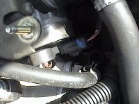
throttle body 4.JPG
So if you're sure the throttle body itself is in good shape then you may have a problem with the throttle body connector or it's connector at the ecu
 
Last edited:
Thanks deckchair, so i take it that bank 1 sensor 2 is the post cat o2 sensor?
I have cleaned with contact cleaner the throttle body connection and the ecu connectors.
I have heard of a throttle re learn or re train how is this done?
the fiatecuscan software shows the throttle position as ok at idle mid and full throttle so the pedal sensor appears to be ok.
I will check the post cat heater element for continuity.
thanks again deckchair..
 
Thanks again deckchair..
I am going down to dads to have another look today. Will try o2 sensor heater resistance first and if duff will order another. Have looked at your link thanks and will try this as soon as the o2 sensor fault is cleared..
Thanks again and will report back.
 
Ok. Post cat o2 sensor faulty. open circuit on the heater. Checked i was doing it right by checking the pre cat sensor (that one measured 8.7 ohms).
Need to order a new one. Anybody know a good quick supplier i can order from.
When it's fitted i will reset ecu codes and try the throttle re learn proceedure that deckchair pointed out to me earlier (thanks)
I will post again when i get any further.
 
Post cat o2 sensor faulty. open circuit on the heater. Checked i was doing it right by checking the pre cat sensor (that one measured 8.7 ohms).
Need to order a new one. Anybody know a good quick supplier i can order from.
Depends which type you want to go for. If you want to go for one that has the connector already installed then that is type specific and will be £80-90 from most suppliers like Shop4parts, Just Lambda, even Fiat dealer etc
If you want a Universal lambda sensor and connect your own connector to it then they're around £20. They're the same lambda sensor but the biggest problem is with the person installing it:)

The sensor is supplying less than a volt and it's critical for the ECU so they have got to be REALLY GOOD connections and people just generally make a right hash of it, then they blame the lambda sensor.

lambda wiring 1.JPG
So you use heat shrinkable, weatherproof sealing crimp connectors, they're usually supplied with the sensor but people don't heat shrink them on to seal the weather out and then they wonder why it all goes wrong in the wet, staggered so they cannot contact one another and seal the whole lot with a heat shrinking insulating sleeve around the outside (don't forget to slide it on first):)
 
Last edited:
Cheers deck chair.
I have ordered a universal lambda sensor so will do as you say with the crimps and heatshrink. do you think a soldered joint with heat shrink would be ok (I have a background in electrical/electronics so can solder well), Or would you still reccomend the crimps?
 
I think it's best to use the supplied crimps as they should be the better ones with heatshrinking outers and integral heat sealing adhesive so they're pretty good and weatherproof all on their own.

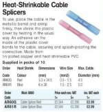
splice connectors.JPG
If they don't come supplied with them then you can get them at Maplins (catalog Page 727). This is price for 10 connectors. They're pretty ninja and would be weatherproof on their own but with a large heat shrink around the whole lot then it's double sealed and also gives it support

When they say "heat in the usual way" then they mean heat gun or something similar

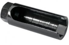
socket.JPG
You'll be best with a special lambda sensor socket with the slit up the side for the wiring. They're around £5
 
Last edited:
Deckchair to the resue yet again. Thanks Dude.
Not sure whether the connectors will arrive with the sensor so have just ordered some from maplin along with some heat shrink tube (adhesive type ) to lock them all together..
I managed to get the sensor out quite easily with an open ended spanner so should be ok to get it back again.
Will post again when everything arrives..
Thanks again
 
Good News o2 sensor changed and that fault is now gone...!
However still have problems..
Now getting a P1687 code and still getting p0638 code. Have done the throttle re learn proceedure but still problems... The idle is very rough and occaisionally get misfire notices on various cylinders.
The p1687 code says it's a pump module is unblocked or ( can't remember the rest of the message ).
Anyone Know what this code means or what else i can do?
Thanks. Flyright
 
[FONT=&quot]P1687 Motorised throttle(stop learn)[/FONT]
[FONT=&quot]P1687 Throttle driven [signal implausible][/FONT]


So it'll come as no surprise that your ecu is having trouble controlling or getting plausible feedback from the throttle body.


throttle body 4.JPG
Anywhere in the circuit from the ecu to the throttle body motor or the feedback from the throttle body potentiometer pots could be causing the problem. Throttle body consists of a motor circuit and two potentiometer tracks which give the throttle valve position

DSC00218.JPG
Give the throttle body connector the wiggle test when it's idling

This isn't exactly yours but it gives a good idea of how it works and what you're looking for
http://www.autoshop101.com/forms/h33.pdf

Or you could watch these very good looking guys telling you in their own riveting way what testing they do but forget about doing the stuff relating to a carburettor
 
Last edited:
Thanks again deckchair..
The throttle body was sent away previously to BBA REMAN for repair and they said it had been tested and was not faulty. I have cleaned all the connectors with contact cleaner and have done the wiggle test on the throttle body connector whilst monitoring the data on fiatecuscan and didn't seem to have any effect.
I will take out the throttle body again (getting quite good at athat now!) and meter it out to see that i am getting the correct readings as per the video (i know it has the two potentiometer setup).
I will report back after looking at it tommorrow.
Thanks again for your time and patience.
 
Ok here goes.. Stripped out throttle body checked the potentiometers at the connector (both ends) both measured 2 ohms at idle to 3.5 ohms full open the measurement was progressive throughout. The motor connections (middle 2 pins on the connector) i could not check. Cleaned the body again (as it was out) and cleaned the connectors on the car at the ecu and throttle body ends. Re assembled the body onto the car and Reset ecu codes. Did the throttle re learn proceedure again but during this the engine light came on on the dash, continued anyway with the proceedure and when done re read the ecu codes. The car still idled very rough with occaisional random misfire codes appearing and the throttle raises the rpm from idle to 2000 ish but other than that is ineffective. Here are the codes...
within 20s of engine start P1686 then sometime after that P0638 and P1687.
The cable from the throttle body to the ecu appears ok with no damage evident but did not want to separate the wiring loom to check end to end.
I'm beginning to suspect the ecu.?
Any help much appreciated. Sorry about the war and peace but wanted to get everything down.
Flyright.
 
Wow! What a nightmare
OK now those resistance figures you're quoting,
checked the potentiometers at the connector (both ends) both measured 2 ohms at idle to 3.5 ohms full open the measurement was progressive throughout
that's much too low with just 1 ohm between max and min so between which pins did you check?
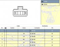
You want to check bet pins 1 and 2 and then 1 and 6

The motor connections (middle 2 pins on the connector) i could not check
You don't say why not? They should check out for near zero resistance across pins 3 and 4 as it's a motor
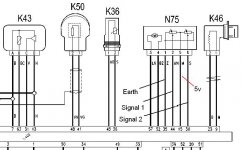
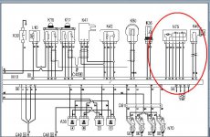
throttle bdy circuit.JPG

throttle body connector pinout.JPG

Never mind. Do you know how to back probe the TB connector? If you do, I'd back probe to see if are you getting the following


5v on the sensor pot supply pin 5?
reference earth at pin 1?
var voltage 0-5v proportional to throttle movement at sensor bet pins 1 and 2 and then 1 and 6?
==========================================
If you are getting 5v at pin 5 then you know the ecu is putting out and supply wiring is good from ECU to TB sensors

0-5v volts between pins 1 and 2 and then between 1 and 6 mean TB pos sensors are tracking and supplying output (but you don't know if that's going back to ecu unless you back probe there too) so you'd need to back probe ECU connector B pins 44 and 30 to check if the TB position signals are being received

Then there's the TB motor but see how you get on with those tests as you really need a good scan tool or oscilloscope to check TB motor power input square wave from ECU
 
Last edited:
Cheers deckchair. Yes it is a nightmare...
I checked between pins 1-2 and 5-6 as all i was checking was the proportional sweep of the pots. I will double check the resistance readings as i was using my cheap multimeter so may have got the scales wrong. The motor was a dead short as it should be. couln't check any further than that. I will back probe the tb connector to see whats going on.
Do you have a pinout diagram of the ecu connectors including which conn is which.
Its the magnetti marrelli ecu.
Thanks again.
 
Sorry Deckchair i don't have wiring diagrams...
I could not get access to the members offers area of the forum.
I don't know why, it just will not let me in. I did spend a good hour trying to download elearn but got p***** off getting passed from download portal to another.

Any other idea's on how to get elearn?
 
Davren's been kind enough to provide an eLearn upload


https://www.fiatforum.com/computing/227364-e-learn-download.html

I never use it myself, can't stand the bloody thing. I think the E stands for egg timer, just sit there looking at an egg timer for ages but you have to have wiring diags, I couldnt do much without them

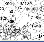
ECU M10 CONNECTOR A AND B.JPG
Here's showing the ECU M10 connectors A and B

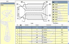
ecu M10 connector A pinout.JPG
Connector A pinout

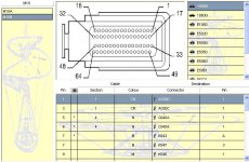
ecu M10 connector B pinout.JPG
Connector B pinout
 
Last edited:
I've just finished the download and burn of the cd. (Thanks davren)
I see what you mean this will make things soooo much easier.
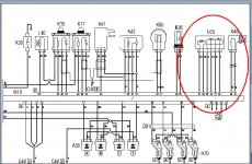
Found conn m10b and the pinouts so can now check the wiring from the tb to the ecu. If these checkout ok then looks like it's either the TB or ecu. I have toyed with the idea of sending both ecu and TB to bba reman for test and repair (if necessary)
What would you think of this? I can back probe the TB but would it just to be quicker to send both off as long as i know the cable is ok?
Your advice would be welcome Deckchair..
Flyright
 
Well it's early days to be pointing the finger at the TB or ECU but be methodical, maybe print off the wiring diag or copy and paste it into Paint perhaps and check off what you've checked out. If the fault is in the wiring then it will be peanuts to repair compared to sending off ECU and TB for investigation
 
Last edited:
Back
Top