Wow! What a nightmare
OK now those resistance figures you're quoting,
checked the potentiometers at the connector (both ends) both measured 2 ohms at idle to 3.5 ohms full open the measurement was progressive throughout
that's much too low with just 1 ohm between max and min so between which pins did you check?
You want to check bet pins 1 and 2 and then 1 and 6
The motor connections (middle 2 pins on the connector) i could not check
You don't say why not? They should check out for near zero resistance across pins 3 and 4 as it's a motor
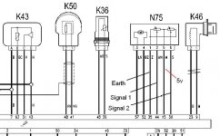
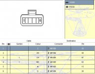
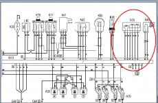
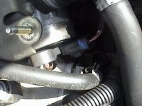
Never mind. Do you know how to back probe the TB connector? If you do, I'd back probe to see if are you getting the following
5v on the sensor pot supply pin 5?
reference earth at pin 1?
var voltage 0-5v proportional to throttle movement at sensor bet pins 1 and 2 and then 1 and 6?
==========================================
If you are getting 5v at pin 5 then you know the ecu is putting out and supply wiring is good from ECU to TB sensors
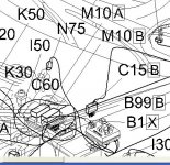
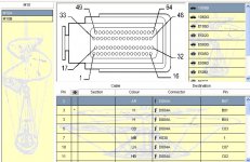
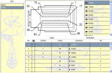
0-5v volts between pins 1 and 2 and then between 1 and 6 mean TB pos sensors are tracking and supplying output (but you don't know if that's going back to ecu unless you back probe there too) so you'd need to back probe ECU connector B pins 44 and 30 to check if the TB position signals are being received
Then there's the TB motor but see how you get on with those tests as you really need a good scan tool or oscilloscope to check TB motor power input square wave from ECU
