M misu Member Joined Dec 16, 2014 Messages 30 Points 67 Oct 28, 2017 #1 I wonder if anyone has the circuit diagram in the left-hand drive to the headlamp, changed to another and still works.
I wonder if anyone has the circuit diagram in the left-hand drive to the headlamp, changed to another and still works.
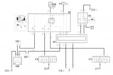
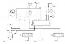
Davren Moderator Staff member Uploaded 10+ resources/downloads Joined Jul 6, 2008 Messages 16,366 Points 3,858 Location London, UK. Oct 28, 2017 #2 Wiring diagrams for the dipped and main beam headlamps are below. F10 is the left headlamp. F11 is the right. . Attachments Dipped Headlamp.JPG 88.8 KB · Views: 26 Main Beam Headlamps.JPG 90.6 KB · Views: 20
Wiring diagrams for the dipped and main beam headlamps are below. F10 is the left headlamp. F11 is the right. .
OP OP M misu Member Joined Dec 16, 2014 Messages 30 Points 67 Oct 29, 2017 #3 Davren said: Wiring diagrams for the dipped and main beam headlamps are below. F10 is the left headlamp. F11 is the right. . Click to expand... It's ok! but I need the circuit at the headlamp adjustment motor.
Davren said: Wiring diagrams for the dipped and main beam headlamps are below. F10 is the left headlamp. F11 is the right. . Click to expand... It's ok! but I need the circuit at the headlamp adjustment motor.
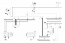
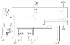
Davren Moderator Staff member Uploaded 10+ resources/downloads Joined Jul 6, 2008 Messages 16,366 Points 3,858 Location London, UK. Oct 30, 2017 #4 misu said: It's ok! but I need the circuit at the headlamp adjustment motor. Click to expand... First diagram below is for normal headlamps. Second diagram is for original Xenon HID headlamps. . Attachments Headlamp Adjustment Motors.JPG 99.7 KB · Views: 12 Headlamp Adjustment Motors HID.JPG 94 KB · Views: 16
misu said: It's ok! but I need the circuit at the headlamp adjustment motor. Click to expand... First diagram below is for normal headlamps. Second diagram is for original Xenon HID headlamps. .