Technical Stilo heater fan

Currently reading:
Technical Stilo heater fan

puck304

New member
Joined
Jul 20, 2008
Messages
38
Points
12
Location
Bournemouth
Hi all,

I have the dual zone climate control with AC. The temperature is fine. The fan output is crap. (n) The fan turns on and off. It come on when you turn it on, then maybe one level more as you increase the level and it stays at that level all the way up through the display.
I took it to a non-main dealer Fiat garage, who are good; they plugged the diagnostic kit in and it threw up a few fault codes:

B1922 Electric fan feedback present, O.C. or S.C. to Ground or Rotor blocked
B1907 Feet/vent flap actuator Intermittent Rotor Block
B1906 Feet/Chest motor feedback.Present O.C. or S.C. to +Batt.V.

Deckchair 5, you say 'B1922 Sounds like the fan is struggling electrically either with a physical restriction (might be leaves in fan) or the speed control CB in the fan motor on climate control cars. The B1906 and 7 are either sticking motors/ sticking vanes or poor wiring contacts on the B1906.'


I've replaced cabin filter and stuck a hoover nozzle in there too. When I first did that when first getting the car last year, there wasn't a cabin filter in there :bang:
Sounds like I need to pull the fan out then?
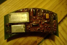
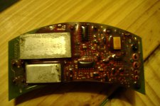
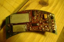
If there's no leaves in there, what would I need to look for on the speed control CB?
Could anyone also explain a bit more about 'The B1906 and 7 are either sticking motors/ sticking vanes or poor wiring contacts on the B1906'?

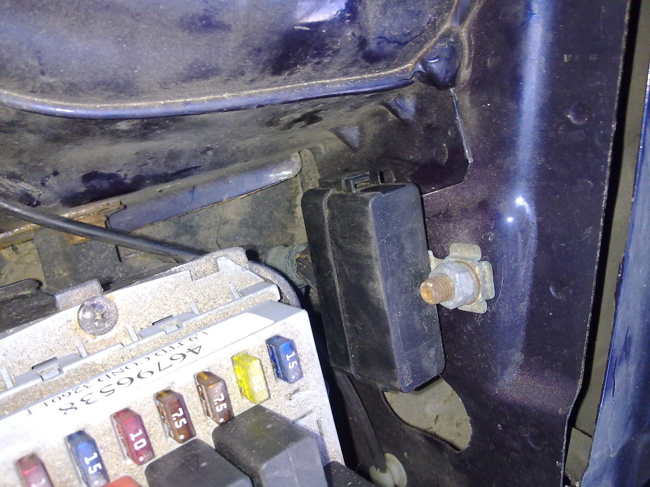
I've disconnected the connector to the fan, and put a multimeter across the feed and earth outputs; it shows just over 12V. The fuse by the battery looks ok and I cleaned up the contacts on the relay. I don't how to test the relay or how it would show itself to be faulty?:confused:


If you're not getting the higher fan speeds then you'd need to inspect fan speed controller circuit board on the fan for damage. They are often attacked by water/acid in there which warps the board and causes open circuits
DSCN4235SML.JPG

B1907 means the vane rotor is blocked from moving- either the vane paddle is broken or the drive cog is broken. Something is preventing it moving

B1906 means a circuit problem at the motor- poor contact causing open circuit most likely or even a short circuit
 
Last edited:
Hi, thanks for your reply. If the circuit board is warped or damaged like you say, is that repairable?
 
Hi, right, I got the fan out, that's a bitch of a job. Tried putting 12V from a car battery on the input to the circuit board, nothing but sometimes a small blue spark. Took the fan out the casing, few leaves and debris around the windings end, bit of switch cleaner. Circuit board filthy, gave it the same treatment with the addition of an old toothbrush.

With the circuit board unplugged, I connected the battery direct to the fan terminals, and it spun great! Tried plugging the circuit board back in, nowt.

So, the circuit board seems suspect? Any ideas on that, as it looks ok, but I don't know how to check it.:confused:
 
Do a close up visual check with a magnifying glass for physical damage, warping and lifting of the circuit board and any dark discoloured areas showing signs of oveheating

Electrically try to trace the circuit board tracks and check for continuity by simple resistance checks to see if there are any open circuits ie breaks along the tracks. People who found breaks in the tracks soldered in a simple bridge

Simulating input voltages and reading outputs would be the next step but that means a through understanding of the circuit and being able to simulate those voltages
 
Thanks, do I have to peel that plastic off, or just push through with a probe? What am I looking for with 'continuity checks'?
 
Do whatever it takes to gain access but with the minimum of damage
But before you do, cary out some input and output checks.
fan wiring.JPG
Check you have a good earth going through to earth point C16 from the fan circuit board connector pin 3 (black wire). Check you have 12v arriving on the red wire there pin 4
See what happens at the pin 2 (white+blue) as this is the request speed voltage and then pin 1 (light blue/green) is the return motor speed signal telling what speed the fan is actually doing

Continuity means "is there a continuous connection in the circuit" like a switch, turn the light on and you have continuity in the circuit, turn it off and you have no circuit

The fact the fan fault code B1922 tells you that the motor is not getting up to the requested speed means there is a confict between what the motor is being told to do and actually doing it, that's why it suggests there might be fouling of the fan or short or open circuits there but a poor earth connection would produce the same fault of a lower than requested fan speed
 
Last edited:
Sorry to appear dim here, but to check earth, is that checking resistance between the 2 points and for it to be zero? :eek:
I do have 12V showing at the connector end of the loom that feeds the CB.
To check pin 1 and 2, do I connect (+) end of a multimeter to each of them and the (-) on pin 3?
I had a closer look at the CB when I cleaned it up a bit, and without a magnifying glass, I could only see what I've circled that looks suspect.
Thanks again!
 

Attachments

  • DSCF3014.JPG
    DSCF3014.JPG
    289.6 KB · Views: 152
  • DSCF3015.JPG
    DSCF3015.JPG
    276.4 KB · Views: 126
  • DSCF3016.JPG
    DSCF3016.JPG
    265.7 KB · Views: 127
Sorry to appear dim here, but to check earth, is that checking resistance between the 2 points and for it to be zero?
redface.gif

Yes.
Ok step by step
with the fan connector N85 disconnected
Multimeter (MM) set to voltage
Check you have 12v arriving on the red wire there pin 4
Multimeter (MM) set to resistance
Check you have a good earth going through to earth point C16 from the fan circuit board connector pin 3 (black wire). Check between pin 4 and bare metal earth like the seat mounting bolts. Should be near 0ohms. This is a vitally important check as your car is also warning of open circuit to ground ie something wrong with it

Even better, do a voltage drop check on pin 4. This is simply checking that there is no voltage on the earth line which is a better indicator that you have a good earth. Here's how
Connect the N85 fan connector to PCB. Have it somewhere safe where it won't touch any metal and short to ground
Multimeter (MM) set to voltage
Now you are going to back probe- ie slide a pin alongside the black wire at the connector down into the connector so it makes electrical contact.
Ok now with ign on check for near zero volts between the pin and the same bare metal earth. Above 0.3v might show a problem there

If both tests are good then you have good power supply and earth

To check the pcb output then unfortunately you would need an ocscilloscope as it looks like a closed loop pulse dc motor controller ie it's sending out pulses of 12v to control the fan speed and closed loop means it has feedback as to what speed the motor is doing but see how you get on with the steps above and really make sure that earth is good.

If your PCB pics were much brighter and much more high def and showing BOTH sides of the pcb then we could have a close look for you but don't worry if you can't as it would only show a suspect area that you would need to investigate.

Check that earth line!
 
Last edited:
Hello again, 2 things I need to clarify:

1. 'Check you have 12v arriving on the red wire there pin 4' DVM (+) probe on pin 4, (-) probe on pin 3?

2. When you say:

'Check you have a good earth going through to earth point C16 from the fan circuit board connector pin 3 (black wire). Check between pin 4 and bare metal earth like the seat mounting bolts.'

Is C16 to pin3 as one check, and pin 4 to seat mount bolt as another check? Or is by checking pin4 to seat mount bolt telling me about C16 to pin 3?

If they are seperate, then do I need a long length of wire from C16 to pin 4 and if that's the case, then is C16 offside under the bonnet?

Just trying to get it clear in my mind(!), apologies for not understanding completely.
 
is by checking pin4 to seat mount bolt telling me about C16 to pin 3?
No, pin 4 to seat mount bolt ie ground is telling you whether you have 12 v supply with ign on.
Once you have checked that then, with ign off, check resistance of pin 3 to ground which should be near zero ohms. Even better do a voltage drop test as described above

The earth point C16 condition is vital as it gives earth to the heater fan motor but also to the auto climate control module and that might explain why so many aircon fault codes are being stored
C16 earth point.JPG
Drawings show C16 here but they are often wrong
 
Last edited:
As I face a similair problem with my fan I took a picture of the small box that should be the earthing of the airconditioning system. Is this the right place? When I'm in front of the car it's on the right side. next to the battery.
040720111259.jpg
 
That's earth pont C15 which deals with wipers etc but that's not to say the air con and heater circuit doesn't go to it because they do twist things around a bit when changing from lh drive to rh drive and the wiring diagrams seem to get left unchanged
earth points engine bay C15.JPG
I mean what's the point in having a body earth point C15 there when the battery earth terminal is less than 10cm away?
 
Last edited:
I can't see C16 on the drivers side, where is it meant to be? Am I going to have to remove the coolant bottle and other bits to get to it? :confused:

Because I coudn't find it, a mate at work with a multimeter and I tried some checks based on what you suggested. Fan is out of car still at home with PCB.

We put ignition on, connected DVM to pin 3 and 4. 12V present.
We did the same with DVM connected to pin 4 and seat mount bolt. 12V present.
And again, DVM to pin 4 and ground on cigarette lighter. 12V present.(y)

We set the DVM to resistance. Pin 3 and seat mount bolt. 0.003 or 0.03ohms (can't quite remember). Similar between Pin 3 and earth on cigarette lighter.

Haven't done the voltage drop yet as PCB was at home, hope to try that tomorrow when I'm back at work.

We then connected the DVM to Pin 1. Nothing, as we thought that the fan would need to be connected as you say it's the return motor speed signal, and I guess it needs to have it connected to have a signal to feed back?

We then connected the DVM to pin 2 (request speed voltage), and measured the outputs as we stepped up through the fan speed control:
0.019
1.128
1.694
1.807
2.260
2.656
3.052
3.449
4.241
4.354
4.524
4.694
5.679
Are these correct? I'm going to try the same tomorrow with the PCB connected but measure the output of the PCB to the fan itself, would that be of use?
 
Lots of questions there but your test figures look good. You have proven a good 12 v supply and earth and the speed request signal of gradual varying voltage looks good. The fact you have proven there to be a good earth connection means you do not need to find the source of the earth C16 as you know it's good. But if you wanted to prove it's at C15 then simply do your earth resistance check from the heater fan earth as before and disconnect the C15 mounting nut and pull away from the car body. If the resistance suddenly rises then it proves that be the earth point

So signs would indicate a bad heater fan speed circuit board but this is really where you could do with an oscilloscope to see the output as I believe it will be a pulsed square wave 12v to control the fan speed
 
Is there anything I can do without an oscilloscope?
If I did have one, would I need to have the PCB connected to the fan, feed it say 12V from a car battery and measure the output of the PCB to the 'scope?
I'll try and get some better pics of the board as well.
 
Back
Top