Hi does anybody know how to locate the wire going to the battery charge light from the Alternator.
Thanks
Stu
Thanks
Stu


")
So does nobody know of anywhere i can splice from.
I have recently run 5m of 3.0mm wire from the battery, by fitting a ring treminal to the existing battery + bolt and put the nut back over it, into the boot of my JTD for a splitcharge (smart) relay and added a 12S socket to power the lights, fridge & charge the battery on the caravan.
For the relay and wiring kit check out Towsure's W28 Kit, which is what I fitted, figuring that messing with the Alternator wiring would be bad news on a Stilo!
Worst bit... getting the cable through the bulkhead :bang:
That's why I said "NOT the B+" Decks.
Surely all the split charge relay needs is an "engine running" or "alternator charging" signal and that would be available at the D+ terminal of the alternator no matter what system it's fitted to.
Dave.
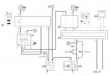
This is the wiring and component location diagrams for the charging and starting circuits from eLEARN.
A10= Alternator - D7= Inline Connector (only fitted on 1.6 engine) - D4= Inline Connector - M1= Body Computer.
Brown wire (M= marrone= brown) goes from terminal D+ on the alternator to pin 1 of inline connector D7 then to pin A6 of the D4 inline connector then to pin 19 of the BC. It's probably a very thin brown wire as it only needs to carry a very low current.
The location diagrams are never very accurate but I would guess that the D7 connector is close to the back of the alternator and the D4 connector (as all Stilo owners know???) is under the engine fuse box.
Dave.
So i would be better off using the D4 to take to Terminal 86 on my Relay.
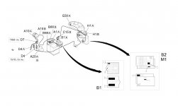
So does anybody have a picture to show me where this D4 connector is or is it the thing that looks like a Can-bus connector underneath the battery.
Also i have always been a little confused as to the alternator main power going to terminal 30 do i connect this via the battery positive.
Thanks guys.