Information taken Elearn
Functional description
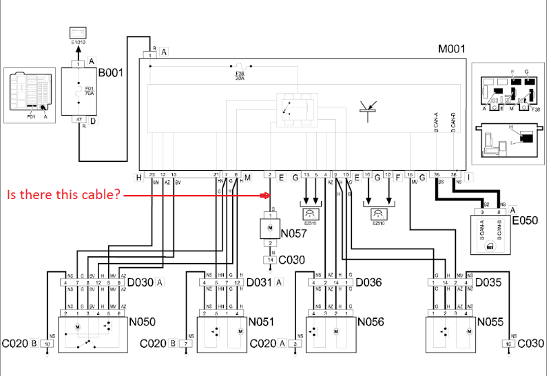
The central locking function is entirely managed by the body computer node M001 which controls the locking/unlocking of the doors depending on the command received by the remote control (where available) or from the driver's front door lock N050.
To lock the doors, the body computer node:
• from pin 12 connector H receives the negative door locking signal (with reference to earth C020 connector B) supplied by the front driver's door lock N050 (pin 6);
• from pin 7 connector M supplies the electric motors for the front door locks N050 and N051;
• from pin 10 connector E supplies the electric motors for the rear door locks N055 and N056.
Earth C020 is fastened to the passenger compartment floor and is located near the right front wheel arch (footwell area).
To unlock the doors, the body computer node:
• from pin 13 connector H receives the negative door unlocking signal (with reference to earth C020 connector B) supplied by the front driver's door lock N050 (pin 3);
• from pin 6 connector M supplies the electric motors for the front door locks N050 and N051;
• from pin 9 connector E supplies the electric motors for the rear doors N055 and N056.
The power supply for the electric motors for each individual door lock (front, rear and boot) is protected by fuse F38; the door locking/unlocking logic is managed by a relay incorporated in the body computer node.
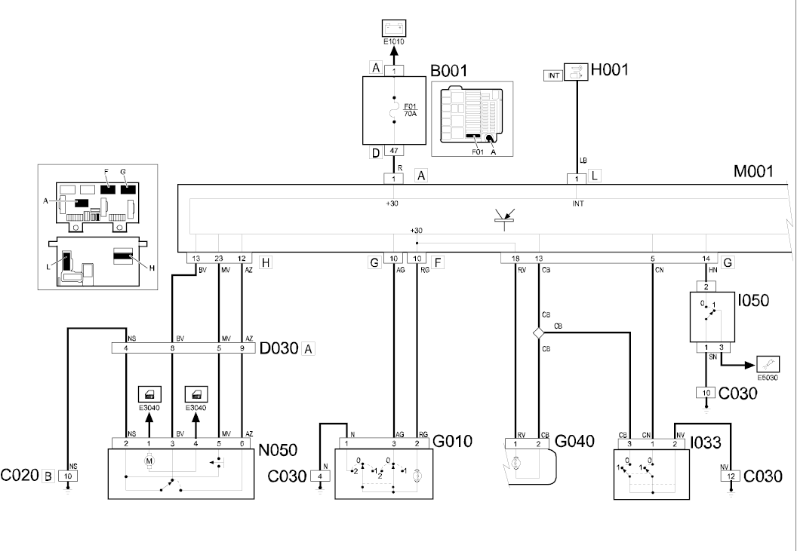
The body computer supplies the electric motor for the boot lock N057 from pin 2 connector E. The command for opening the tailgate arrives from switch I033 at pin 5 connector G of the body computer node M001 (see wiring diagram E2510).
The body computer node also checks that each individual door is correctly shut by means of the signals supplied by the internal (normally open type) switches for the door locks.
More precisely, one door is considered as open (or not properly shut) when the body computer:
• receives a negative signal, from pin 23 connector H, (with reference to earth C020 connector B), coming from lock N050 (driver's front door check);
• receives a negative signal, from pin 21 connector H, (with reference to earth C020 connector B) coming from lock N051 (passenger front door check);
• receives a negative signal, from pin 4 connector G, (with reference to earth C020 connector A), coming from lock N056 (right rear door check);
• receives a negative signal, from pin 15 connector G, (with reference to earth C030), coming from lock N055 (left rear door check).
• receives a negative signal, from pin 13 connector G, (with reference to earth C030), coming from switch I033 (tailgate check, See E2510 COURTESY LIGHTS ).
Door couplings D030 and D031 are housed in the lower part of the front pillar (right or left depending on the coupling involved), near the door cable duct.
In german:
Funktionsbeschreibung
Die Funktion der Türverriegelung wird komplett vom Knoten Body Computer M001 verwaltet, der die Ent-/Verriegelung je nach erhaltenem Befehl von der Fernbedienung (wo vorgesehen) oder dem Fahrertrschloss N050.
Der Knoten Body Computer, für die Türverriegelung:
• erhält von Pin 12 Stecker H das negative Signal der Türverriegelung (in Bezug auf Masse C020 Stecker B), das vom Fahrertürschloss N050 (Pin 6) geliefert wird.
• versorgt von Pin 7 Stecker M die elektrischen Motoren der Vordertürverriegelungen N050 und N051.
• versorgt von Pin 10 Stecker E die elektrischen Motoren der hinteren Türen N055 und N056.
Die Masse C020 ist am Boden, im Innenraum, in der Nähe des Radkastens vorne rechts (Fußbereich) befestigt.
Der Knoten Body Computer, für die Türentriegelung:
• erhält von Pin 13 Stecker H das negative Signal der Türentriegelung (in Bezug auf Masse C020 Stecker B), das vom Fahrertürschloss N050 (Pin 3) geliefert wird.
• versorgt von Pin 6 Stecker M die elektrischen Motoren der Vordertürentriegelungen N050 und N051.
• versorgt von Pin 9 Stecker E die elektrischen Motoren der hinteren Türen N055 und N056.
Die Versorgung der elektrischen Motoren jedes Türschlosses (vorne, hinten und Kofferraum) werden von der Sicherung F38 geschützt; Die Ver-/Entriegelungslogik der Türen wird von einem Relais im Knoten Body Computer verwaltet.
Von Pin 2 Stecker E versorgt der Knoten Body Computer den elektrischen Motor des Kofferraumschlosses N057. Der Befehl für die Kofferraumöffnung kommt vom Schalter I033 an Pin 5 Stecker G des Knotens Body Computer M001 (siehe Schaltplan E2510).
Der Knoten Body Computer kontrolliert ausserdem das korrekte Schliessen jeder einzelnen Türen durch die Signale, die von den Türschaltern (Typ normal offen) in den Schlössern geliefert werden.
Genauer ist eine Tür offen (oder nicht richtig geschlossen), wenn der Knoten Body Computer:
• von Pin 23 Stecker H ein negatives Signal (in Bezug auf Masse C020) vom Schloss N050 (Kontrolle Fahrertür) erhält.
• von Pin 21 Stecker H ein negatives Signal (in Bezug auf Masse C020) vom Schloss N051 (Kontrolle Beifahrertür) erhält.
• von Pin 4 Stecker G ein negatives Signal (in Bezug auf Masse C020 Stecker A) vom Schloss N056 (Kontrolle Tür hinten rechts) erhält.
• von Pin 15 Stecker G ein negatives Signal (in Bezug auf Masse C030) vom Schloss N055 (Kontrolle Tür hinten links) erhält.
• von Pin 13 Stecker G ein negatives Signal (in Bezug auf Masse C030) vom Schalter I033 (Kontrolle Hecktür Siehe E2510 INNENLEUCHTEN ) erhält.
Die Türverbindungen D030 und D031 befinden sich im unteren Teil der vorderen Säule (rechts oder links je nach Verbindung), in der Nähe der Türkabelführung.


")