parts/tools required:
leds:
now you want 3mm leds in ultrabright.
avoid maplin and lower output led's as these are not really suited
ive used these suppliers so these are trusted by me
http://stores.ebay.co.uk/phenoptix
http://stores.ebay.co.uk/Goodwill-Leds-Sales_W0QQsspagenameZL2QQtZkm
http://www.ultraleds.co.uk/(also does the bulbs for the instrument lights)
of course there are other sellers.
a seller of complete units on ebay is http://stores.ebay.co.uk/Crazy-LEDS
but why read the guide if your not doing it yourself
you can get diffused led's so you dont get a bright tip on the led however if need be you can sand down the tip of the led to frost the tip.
another method is to apply a little hot glue to the tip
a little info on led's so you know whats what if your reading up
leds have 2 legs,one of which will be longer.
anode is the positive leg and is usually longer
cathode is the negative and is shorter than the anode
if you want ot test an led or check which is the positive leg then use a flat watch battery
LED basics
heres a great resistor calculator which can even do circuit diagrams
- soldering iron:if your doing a little soldering i like this little antec one
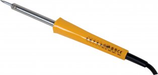
- its not too hot and nice and light to work with.
- beware cheaper irons as they tend to run hot which can lead to problems for someone new to soldering
- wire cutters for snipping led legs if required
- a small sponge to clean the solder tip
- small flat bladed screw driver
- posi drive screwdriver
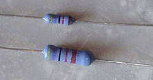
- resistors(if you plan on doing other led mods)
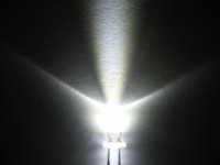
- 3mm leds
- optional if you solder more often
- tip cleaner
- flux
- desoldering braid/solder sucker
- hot glue gun
leds:
now you want 3mm leds in ultrabright.
avoid maplin and lower output led's as these are not really suited
ive used these suppliers so these are trusted by me
http://stores.ebay.co.uk/phenoptix
http://stores.ebay.co.uk/Goodwill-Leds-Sales_W0QQsspagenameZL2QQtZkm
http://www.ultraleds.co.uk/(also does the bulbs for the instrument lights)
of course there are other sellers.
a seller of complete units on ebay is http://stores.ebay.co.uk/Crazy-LEDS
but why read the guide if your not doing it yourself
you can get diffused led's so you dont get a bright tip on the led however if need be you can sand down the tip of the led to frost the tip.
another method is to apply a little hot glue to the tip
a little info on led's so you know whats what if your reading up
leds have 2 legs,one of which will be longer.
anode is the positive leg and is usually longer
cathode is the negative and is shorter than the anode
if you want ot test an led or check which is the positive leg then use a flat watch battery
LED basics
heres a great resistor calculator which can even do circuit diagrams
right the hands on bit
Remove all the dash switches including the headlight switch. remembering where each one go's.
on the push switches pull the bulb holder from the back of the switch.
pull the LED by the bulb and completely remove it noting the resistor on the bottom of the holder.
with your new LED insert the legs into the guides. the longer of the LED legs go's with the resistor. THIS IS ESSENTIAL FOR THEM NOT TO BLOW.
re-insert the holder into the switch. there should only be one way it will fit back in, but if not the resistor go's at the bottom.
repeat for all push type switches and fit them back in the dash.
the headlight switch: you will either need to de-solder or cut the existing LED out.
you will also need to cut your new LED down to size but also make a note of which is the longer leg.
the longer leg of the LED needs to be soldered to left contact(working from the behind the switch).
finally solder the other leg and push the LED into the same position as the original.
BE CAREFUL NOT TO MELT THE PLASTIC OF THE SWITCH WHEN SOLDERING!
re-fit into the dash and test.
WARNING: if you inend to change speedo etc bulbs for leds then do not change the ECU warning bulb or the battery bulb.
the resistance difference will cause you problems
right so fairly simple but if you want to go beyond that.
if you want to led your footwell for example.
(this is off the top of my head but gives you an idea)
make 2 strips from wood,plastic or as i would use
matrix board from maplins
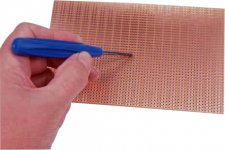
but not the copper based stuff,just plain.
this can be cut,dremeled,sanded etc very easily
the holes are perfect to fit led's into.
so make your 2 strips and push the leds through the board.
leave 2 holes between each led.
it will be explained further down but if you for one resistor per led then bend the leds so they are @ 180o to the board but if its in parallel then either 180o or 90o as it doesnt matter.
make sure you keep the long leg/short legs to the same sides
so you have one row of + and one row of negative
now theres 2 options for resistors here
1 resister per led.
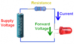
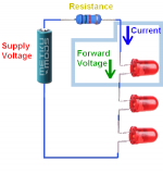
or 1 per strip(in series)
or you can go parallel(not in my example)
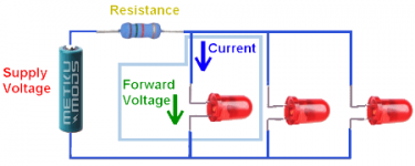
when i do them I do one per led but i like this is its easier to change stuff plus it cut down the amount of resistors i had to stock
if you go for 1 per strip this is wiring in series.so the above resistance calculator will tell you the rated resistor required
so you have your strip with leds inserted along its length
bend the legs out on each LED to keep them in place
now get some single core wire (i use kynar) and solder one complete wire to the negative legs (on the underside of the board)of all the leds's on one board.
repeat for the other one
now if you go for one led per led it gets a little labour insensive
take one resistor and solder to the positive leg of an led.
slder as close to the actual resistor as possible and then pass the other end of the resistor wire through the board to the underside.
repeat fro all the leds.
now solder a wire along all the resistor ends underneath to make the positive connection
if you are doing 1 resistor per board then just solder a wire along all the positive legs like you did for the negative but solder the resistor in after you have soldered all the legs
test each board by passing current from a 9v battery over them(remember they will be brighter in 12v)
if any led's dont work then check the soldering
once its all working i recommend hot glueing the underside and if done with 1 led per led hotgluing between each led.
then its a case of mounting whereever you chose and connecting to a 12v source with a switch if you want.
this pic gives an idea(poor pic and in an xbox though)
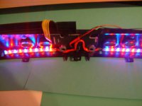
and in a fully assembled state

calculating resistor ratings
for reference and to give you an example here are some resistor ratings for led ratings.
so ive picked a few from ultraleds.
3mm green waterclear
4000-6000MCD- this is the brightness so the higher to number the brighter
the important bits
current 20MA
forward voltage 3.5 to 6V
supply voltage in the car will be 12 volts
so using the higher supply voltage of 6v,current @ 20MA and supply volts @ 12V
requires a 300 ohm resistor but add 10% for safety so 330 ohm
now on the white 10000MCD 3mm LED it can handle less forward volts
so is 3.4 to 3.8V
and same current & supply volts
gives 410 ohms + 10% = 470ohms resistor required
red frosted led's handle even less forward volts @ 2.2v
so requires a 490 ohm + 10% = 560 ohm resistor required.
you can see theres no great variable as you see but always check and punch the numbers into the resistance calculator
now if you are going in series its the same but using the in series calculator
so for the red frosted leds.
forward volts 2.2v
current 20MA
supply volts 12V
but now the no. of led's is a factor so lets say 5 leds.
so this requires a 56 ohm resistor per 5 leds.
remeber theres a limit to how many led's you can use in one series and in this case 5 is really the limit.
the calculator keeps you right though

