Have received a few requests for the guide I wrote out for myself next time I need to do this job so here it is -
I have attached some pictures but these are not in order or that good because of the limited visibility & accessibility on the Ducato. Hopefully my step by step guide will have sufficient info to make up for the lack of step by step pictures.
Timing Belt Replacement Ducato 2.8 JTD 2003
Here is my step by step guide & what I encounted in changing the timing belt on a 2003 Ducato 2.8 JTD fitted with A/C.
As this is a JTD Common Rail Electronic Injection there is no injection pump timing to set (thank heaven). With the 2.8TD it would necessitate the upper timing cover & associated parts removal to enable enough room for timing of the Injection pump.
1. Disconnect the battery, remove front engine cover by undoing the 2 retaining clips.
2. Remove engine top cover , which necessitates the removal of part of the engine lift bracket retaining the 4 electrical cables for the injectors at the bottom right corner as the top cover has a projection under the wiring so cannot be removed until the part of the bracket is moved out of the way. I also removed the bracket bolted to the intake manifold behind the cover as it has some wiring harness retaining clips & two studs with nothing attached to either which hinders easy removal otherwise.
NB: On reinstallation of this bracket I bent the mounting lugs (& removed the studs) so that the two large plastic wiring loom clips could be used to support the coolant bypass pipe that crosses over from the thermostat housing to the front of the engine. This was done because I had asked the parts department at the local Fiat dealer what was the most common thing that went wrong with the 244 Ducato. Apparently out here, it is this pipe cracking from the vibration - which it certainly does, I was told it was $400!! to replace. Think I would use a rubber hose instead for that money.
NB: It is not possible to remove the top timing cover unless the RH (front) engine mount is removed but it is apparently still possible to remove & install the belt regardless even with A/C fitted, this is the method I used but it would be much easier with the engine mount removed especially with A/C fitted. Now as I was doing this alone I needed to have some way of locking the flywheel while I loosened the crankshaft bolt & lock crank during belt removal/installation so I removed the starter motor & made a locking tool anchored with 2 of the starter bolts which worked well. It consisted of a piece of flat steel with a projection welded in the centre to engage with the ring gear on the flywheel – see pic.
3. Remove the bolts for the A/C pipe bracket, bolts for the top timing cover (2 topside, 1 under) & remove the bolts for the Power steering reservoir & move to one side DO NOT DISCONNECT THE HOSES.
4. Then rotate (in the direction of engine rotation) the crankshaft (will need a 36mm socket) & line up the timing marks on the camshaft with the one on the cylinder head under the camshaft position sensor. You cannot see the crankshaft sprocket marks to line them up until the crank bolt is loosened & the pulley removed as the pulley has no timing marks & it is not located in a fixed position on the crankshaft.
5. Loosen the bolts for the A/C tensioner, the pivot bolt for this is 15mm (not a common socket size in my sets) & adjusting bolt & remove the belt marking the direction of rotation on the belt, then loosen the 3 bolts for the alternator adjustor (accessed from underneath with a 13mm &12mm socket & extension bars & from the wheelwell using 13mm spanner above the drive shaft) & then remove the alternator belt again marking the direction of rotation on the belt.
6. Then loosen the 36mm crankshaft bolt (normal RH thread) with the flywheel locked using whatever method - be careful not to drop the pulley (it is pretty heavy) when the bolt is removed as it only sits in a small recess on the crankshaft with a thin spacer between it & the crank & can easily fall off.
You can now see whether the timing marks line up. There seems to be confusion with the timing marks as the Autodata specs I have states “ensure crankshaft sprocket dowel pin aligned with projection on timing belt lower cover (9)”. As there are 2 marks on the sprocket - the keyway & a “Dot” directly opposite. From information from the local Fiat dealer it is the “Dot” that is the mark not the keyway (dowel pin?). The “Dot” is what always lines up anyway, after numerous rotations of the crankshaft. If you get a genuine replacement belt it has the direction of rotation & 2 white lines marked on it to line the two timing marks up to as it is installed (whether the aftermarket belts are the same I don’t know). I would also mark the original belt before removal for comparison with the new one or in case the replacement belt has no markings.
7. Remove the Tensioner nut (17mm), the lower timing cover bolts 10 mm (3) & then the lower cover. Loosen the tensioner bolt (13mm) which is behind the lower cover & lever the tensioner pulley away from the belt, (it doesn’t move very far as can be seen in the pic) retain the tensioner in position with an adjustable wrench or improvise or use the proper tensioner locking tool if available & then remove the timing belt. I used a small pair of vice grips - in the photo of the tensioner assembly which is actually installed into the bottom of the water pump, when pushing the bracket that the tension pulley is attached to back, the small ‘T” (about the size of a 10 cent piece) on the left is where the “Tool” is installed to hold the spring tension off the tension pulley while removing/refitting the belt.
NB: Now with air conditioning installed this process is easier with two people as it is difficult to get the old belt off through & around the protruding pump pulley bolts & the cover projections & in retrospect it is probably easier to remove the engine mount so the cover can be removed & also easier if the A/C pipe is disconnected from the compressor necessitating regasing but it is the engine mount & top timing cover that are the main problem. The same applies to installing the new belt although much easier than removal – a two person job as well.
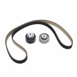
8. Fit the new pulleys which really is compulsory when installing a new belt (on close examination I could not see anything wrong with the old belt or the two pulley bearings @ 43K & 6 years) & tighten the idler pulley bolt (15mm) to specified torque.
9. Ensure the timing marks are still lined up, you need to temporarily install the lower cover again (if flywheel is locked I would think it is not really necessary as it cannot move) & recheck that the camshaft marks line up, fit the new belt starting at the crank, installing anticlockwise to pump, idler pulley & then the cam sprocket, tensioner pulley & back to crankshaft (if using a genuine belt the 2 white lines on the belt should line up with the 2 timing marks when installed correctly, if it is 4 teeth out on the camshaft sprocket the belt needs to be rotated 180 degrees in regard to the white lines).
Install the lower timing cover & bolts (3) & tensioner nut then the crankshaft pulley & bolt (hand tighten) Remove tensioner locking tool or “adjustable wrench tool”.
Slowly turn the crankshaft two turns in direction of rotation & remove crankshaft pulley bolt & pulley, ensure the two timing marks (the “dot “on the crankshaft) & camshaft still line up (the two white lines on the belt won’t line up again) tighten the tensioner bolt (25 Nm) which needs to be done before installing the lower cover & its bolts & tensioner nut (37-47Nm) Reinstall crank pulley & bolt. Lock the flywheel & tighten the crankshaft bolt to 200 Nm. I did do a half a dozen manual rotations to ensure that there were no lockups with the valves hitting the pistons!
Another problem I encountered was once the belt was on past all the projections etc I put the new top idler pulley on first but it was then “very difficult” to get the tension pulley on with the limited space & limited access & slackness in the new belt under the vehicle so I took the idler off & got the tension pulley on first & then again with some difficulty the top idler pulley second. I had the same problem with both pulleys in that with it pressed against the new belt it binded against the belt, which made it hard to slide the new pulley on to the very close fit on the bearing anchor. I used a” very thin” layer of water based lubricant on the part of the pulley in contact with the belt which did the trick & then wiped it off immediately. So maybe the pulleys should be installed first, and then the belt is installed down through the cover as it would be if not replacing the pulleys, although you would probably still have the same problem?
NB: The lower tensioner pulley has ½ width anchor & 2 “washers” the internal one has a ridge which fits in the inner bearing hole (same diameter as the anchor) & will need something sticky to retain it in place (I used a small amount of silastic) while the thicker washer with stud sized hole is also installed next over the tensioner pulley stud to keep it in place (as well as the bottom Timing cover) & the flat/spring washer & nut are then installed & tightened, this arrangement may have something to do with easier installation of the belt?.
10. Reinstall main components to enable the engine to start & run in the reverse order of removal & start the engine. If everything is OK then complete the reinstallation of all remaining components, top engine cover, brackets, underside engine guard etc
I purchased the genuine parts (Belt & pulleys) for the 2.8 JTD Iveco Turbo Daily, as in out here in Oz they are 30%-40% cheaper than buying the Fiat ones from the same dealer & a couple of the part numbers are even the same.
NB: As this is an interference engine if you are not sure what you are doing, & are not comfortable with doing it yourself get a qualified Mechanic/Garage to do it as if it is not installed correctly it will be very expensive to fix the damage! But this guide might give those of you with sufficent expertise to give it a go yourselves.
NB: I take no responsibility for any damage resulting from using this guide - use it at your own risk.


I have attached some pictures but these are not in order or that good because of the limited visibility & accessibility on the Ducato. Hopefully my step by step guide will have sufficient info to make up for the lack of step by step pictures.
Timing Belt Replacement Ducato 2.8 JTD 2003
Here is my step by step guide & what I encounted in changing the timing belt on a 2003 Ducato 2.8 JTD fitted with A/C.
As this is a JTD Common Rail Electronic Injection there is no injection pump timing to set (thank heaven). With the 2.8TD it would necessitate the upper timing cover & associated parts removal to enable enough room for timing of the Injection pump.
1. Disconnect the battery, remove front engine cover by undoing the 2 retaining clips.
2. Remove engine top cover , which necessitates the removal of part of the engine lift bracket retaining the 4 electrical cables for the injectors at the bottom right corner as the top cover has a projection under the wiring so cannot be removed until the part of the bracket is moved out of the way. I also removed the bracket bolted to the intake manifold behind the cover as it has some wiring harness retaining clips & two studs with nothing attached to either which hinders easy removal otherwise.
NB: On reinstallation of this bracket I bent the mounting lugs (& removed the studs) so that the two large plastic wiring loom clips could be used to support the coolant bypass pipe that crosses over from the thermostat housing to the front of the engine. This was done because I had asked the parts department at the local Fiat dealer what was the most common thing that went wrong with the 244 Ducato. Apparently out here, it is this pipe cracking from the vibration - which it certainly does, I was told it was $400!! to replace. Think I would use a rubber hose instead for that money.
NB: It is not possible to remove the top timing cover unless the RH (front) engine mount is removed but it is apparently still possible to remove & install the belt regardless even with A/C fitted, this is the method I used but it would be much easier with the engine mount removed especially with A/C fitted. Now as I was doing this alone I needed to have some way of locking the flywheel while I loosened the crankshaft bolt & lock crank during belt removal/installation so I removed the starter motor & made a locking tool anchored with 2 of the starter bolts which worked well. It consisted of a piece of flat steel with a projection welded in the centre to engage with the ring gear on the flywheel – see pic.
3. Remove the bolts for the A/C pipe bracket, bolts for the top timing cover (2 topside, 1 under) & remove the bolts for the Power steering reservoir & move to one side DO NOT DISCONNECT THE HOSES.
4. Then rotate (in the direction of engine rotation) the crankshaft (will need a 36mm socket) & line up the timing marks on the camshaft with the one on the cylinder head under the camshaft position sensor. You cannot see the crankshaft sprocket marks to line them up until the crank bolt is loosened & the pulley removed as the pulley has no timing marks & it is not located in a fixed position on the crankshaft.
5. Loosen the bolts for the A/C tensioner, the pivot bolt for this is 15mm (not a common socket size in my sets) & adjusting bolt & remove the belt marking the direction of rotation on the belt, then loosen the 3 bolts for the alternator adjustor (accessed from underneath with a 13mm &12mm socket & extension bars & from the wheelwell using 13mm spanner above the drive shaft) & then remove the alternator belt again marking the direction of rotation on the belt.
6. Then loosen the 36mm crankshaft bolt (normal RH thread) with the flywheel locked using whatever method - be careful not to drop the pulley (it is pretty heavy) when the bolt is removed as it only sits in a small recess on the crankshaft with a thin spacer between it & the crank & can easily fall off.
You can now see whether the timing marks line up. There seems to be confusion with the timing marks as the Autodata specs I have states “ensure crankshaft sprocket dowel pin aligned with projection on timing belt lower cover (9)”. As there are 2 marks on the sprocket - the keyway & a “Dot” directly opposite. From information from the local Fiat dealer it is the “Dot” that is the mark not the keyway (dowel pin?). The “Dot” is what always lines up anyway, after numerous rotations of the crankshaft. If you get a genuine replacement belt it has the direction of rotation & 2 white lines marked on it to line the two timing marks up to as it is installed (whether the aftermarket belts are the same I don’t know). I would also mark the original belt before removal for comparison with the new one or in case the replacement belt has no markings.
7. Remove the Tensioner nut (17mm), the lower timing cover bolts 10 mm (3) & then the lower cover. Loosen the tensioner bolt (13mm) which is behind the lower cover & lever the tensioner pulley away from the belt, (it doesn’t move very far as can be seen in the pic) retain the tensioner in position with an adjustable wrench or improvise or use the proper tensioner locking tool if available & then remove the timing belt. I used a small pair of vice grips - in the photo of the tensioner assembly which is actually installed into the bottom of the water pump, when pushing the bracket that the tension pulley is attached to back, the small ‘T” (about the size of a 10 cent piece) on the left is where the “Tool” is installed to hold the spring tension off the tension pulley while removing/refitting the belt.
NB: Now with air conditioning installed this process is easier with two people as it is difficult to get the old belt off through & around the protruding pump pulley bolts & the cover projections & in retrospect it is probably easier to remove the engine mount so the cover can be removed & also easier if the A/C pipe is disconnected from the compressor necessitating regasing but it is the engine mount & top timing cover that are the main problem. The same applies to installing the new belt although much easier than removal – a two person job as well.
8. Fit the new pulleys which really is compulsory when installing a new belt (on close examination I could not see anything wrong with the old belt or the two pulley bearings @ 43K & 6 years) & tighten the idler pulley bolt (15mm) to specified torque.
9. Ensure the timing marks are still lined up, you need to temporarily install the lower cover again (if flywheel is locked I would think it is not really necessary as it cannot move) & recheck that the camshaft marks line up, fit the new belt starting at the crank, installing anticlockwise to pump, idler pulley & then the cam sprocket, tensioner pulley & back to crankshaft (if using a genuine belt the 2 white lines on the belt should line up with the 2 timing marks when installed correctly, if it is 4 teeth out on the camshaft sprocket the belt needs to be rotated 180 degrees in regard to the white lines).
Install the lower timing cover & bolts (3) & tensioner nut then the crankshaft pulley & bolt (hand tighten) Remove tensioner locking tool or “adjustable wrench tool”.
Slowly turn the crankshaft two turns in direction of rotation & remove crankshaft pulley bolt & pulley, ensure the two timing marks (the “dot “on the crankshaft) & camshaft still line up (the two white lines on the belt won’t line up again) tighten the tensioner bolt (25 Nm) which needs to be done before installing the lower cover & its bolts & tensioner nut (37-47Nm) Reinstall crank pulley & bolt. Lock the flywheel & tighten the crankshaft bolt to 200 Nm. I did do a half a dozen manual rotations to ensure that there were no lockups with the valves hitting the pistons!
Another problem I encountered was once the belt was on past all the projections etc I put the new top idler pulley on first but it was then “very difficult” to get the tension pulley on with the limited space & limited access & slackness in the new belt under the vehicle so I took the idler off & got the tension pulley on first & then again with some difficulty the top idler pulley second. I had the same problem with both pulleys in that with it pressed against the new belt it binded against the belt, which made it hard to slide the new pulley on to the very close fit on the bearing anchor. I used a” very thin” layer of water based lubricant on the part of the pulley in contact with the belt which did the trick & then wiped it off immediately. So maybe the pulleys should be installed first, and then the belt is installed down through the cover as it would be if not replacing the pulleys, although you would probably still have the same problem?
NB: The lower tensioner pulley has ½ width anchor & 2 “washers” the internal one has a ridge which fits in the inner bearing hole (same diameter as the anchor) & will need something sticky to retain it in place (I used a small amount of silastic) while the thicker washer with stud sized hole is also installed next over the tensioner pulley stud to keep it in place (as well as the bottom Timing cover) & the flat/spring washer & nut are then installed & tightened, this arrangement may have something to do with easier installation of the belt?.
10. Reinstall main components to enable the engine to start & run in the reverse order of removal & start the engine. If everything is OK then complete the reinstallation of all remaining components, top engine cover, brackets, underside engine guard etc
I purchased the genuine parts (Belt & pulleys) for the 2.8 JTD Iveco Turbo Daily, as in out here in Oz they are 30%-40% cheaper than buying the Fiat ones from the same dealer & a couple of the part numbers are even the same.
NB: As this is an interference engine if you are not sure what you are doing, & are not comfortable with doing it yourself get a qualified Mechanic/Garage to do it as if it is not installed correctly it will be very expensive to fix the damage! But this guide might give those of you with sufficent expertise to give it a go yourselves.
NB: I take no responsibility for any damage resulting from using this guide - use it at your own risk.