Technical KriTip's 1.2 16V Sei Project

Currently reading:
Technical KriTip's 1.2 16V Sei Project

Thanks OK then, no worries on that front then. I'll just have to figure out what to use to blank it off :)

Cheers,

Kristian

Just make sure you blank it off well -- no idea what it looks like, but something like tapping it and putting a bolt or something in with locktite would be ideal: 3 bar and a tiny leak = big fire! (n)
 
The fitting is brass, so i got a copper microbore 6mm central heating end cap, that i'm going to solder on.

Should hold up to the pressure ;) Not sure what pressure central heating systems run at though.

Seems a lot easier than tapping tbh and pretty much non destructive.

In the future I may fit a pressure gauge on there.

Kristian
 
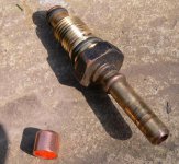
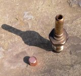
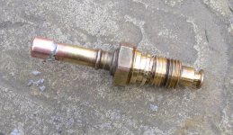
Well, here are pics for my fuel return solution:

P1010803.JPG

P1010804.JPG


The return outlet from the rail and a 6mm microbore central heating cap:


Soldered on to the fuel rail:

P1010805.JPG

Sure it will be up to the pressure and hopefully no leaks. It's my first time at "plumbing" :D I more used to surface mount component soldering (y)


Doing all this fuel stuff got me thinking though about the fuel cannister though.

There are two lines from the tank, one for fuel to the engine. The other for gasses too the cannister in the wheel arm, and then into the inlet to be burnt.

I have no connection for it on the the intake, and i def don't want it venting into the bay :eek:

Hows yours done JR? I think i could poss just blank it and disconnect the wiring? Will it be dangerous or and environmental disaster?


Kristian
 
Does the injector rail have the pressure regulator on it?
If so then the bottom outlet goes to the electro valve, then to the cannister and from there to the fuel tank as the return.
Does the Seicento not have the electro valve inside the cannister?
 
TBH, this whole fuelling thing is confusing me lol

The fuel rail has an inlet, outlet (now capped) and at the other end, a small oulter which is connected to the top part of the air intake and an electronic component with a connector and a little tube.

I don't know where the regulator is to be foound or what these parts are. I should really read the punto manual a bit closer I think, maybe thats tonights job.

I just checked the manual though and it does show a cannister, a controll valve (in line) and a tube to the air intake.

I'll take some pictures later on, and post tonight, if I haven't figured it out already.

I think the Sei mus have the valve in or behind the cannister, as thats where all the wiring is, and between the sei intake and cannister there are no other components (other than possibl behind).

Cheers cc1 for you help :)

Kristian
 
On the 1.2 spi the outlet from the cannister appears to go to the throttle body to recycle the vapour, but on the mpi it seems to go back to the fuel tank.
 
Hmmm,, My reply vanished lol.

I was coming to correct myself but now theres no need as its not here lol.

I have done some more reading and looking.

The cannister has no wiring or solenoid, thats on done right up close to the air intake on the Sei.

The 1.2 16v mk1 MPI does have a feed into the inlet manifold, but it all on the opposite end with different adapters etc. Doh!

Also the vacuum hose is connection is in the front of the intake, so that needs extending.

The various TB/intake connectors of the Sei don't reach where they need to go either :bang:

Therefor its time for a trip to halfords to get wiring, tools, tubing, hose etc. to hopefully carry on today.

I have taken pics for people to see but, as im someone elses pc i can't upload till later.


All will be revealed :D


Kristian
 
Hmmm,, My reply vanished lol.

The various TB/intake connectors of the Sei don't reach where they need to go either :bang:

Therefor its time for a trip to halfords to get wiring, tools, tubing, hose etc. to hopefully carry on today.

I have taken pics for people to see but, as im someone elses pc i can't upload till later.


All will be revealed :D
Kristian


Exactly where I am, infuriating isn't it. The thing on the plenum chamber opposite end of the tb is the map sensor..iirc
I've discovered what I was doing wrong with the hoses, the spi has the heating plumbed into the tb. I was trying to connect this upto the head:bang: Which is actually funny. Your mpi doesn't have heater connections does it?
 
cc1, I can't seem to view that pic, the forum asks for a password :confused: Hopefully it will resolve itself soon :)

dave, your right, there are no heater connections to the TB at all on mine which actally makes something easy :D It looks like all the plubming is going to be fine :slayer:

I think your correct about the sensor.

The MAP is on the one end, where the charcoal cannister conector is as well.

The other end is the TPS opposite the throttle, connected to the butteryfly.

The final sensor is the stepper mottor, idle control.

On the Sei, every single sensor is on the opposite side as to the punto :D so i have all 3 to extend.

I've got to figure out where the breather and vacum connectors are yet though.

The cam sensor reaches fine. The injector cabling fits after removing the cable casing. The oil sensor needs extending (one wire :slayer: )


Sadly my novitec strut brace isn't going to fit :(


Brakes are all back together now :)

So tomorrow, its lots of soldering!

Pics will be uploaded later once I've had a rest and edited them.

Kristian
 
Last edited:
Sorry! picture should be ok now. Some others in the gallery.

Thanks I found those useful too :)

Kristian, you've just resolved some of my plumbing issues :) I've removed my map sensor and plugged in a 2 way vacum take off, I'm using the map from the Punto until I try the Megasquirt. Can you not do something similar
 
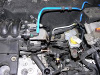
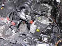
Well, here is a photo of the Sei charcoal cannister outlet, and the valve to open and close it. This is where is would normaly terminate on the sei.
P1010806.jpg
However this shows the MAP and cannister input on the Punto.
P1010808.jpg

I have run fuel hose from the valve to the new input so hopefully that will work although its a bit ungraceful. What shoul dhave been attached the the braket thats sitting there all lonely?

The vaccum hose connects under the plastic housing so I will ahve to fit a different hose there. Does it have to be hard walled like the current hose? Or will and old fuel line or simialar work. I do like assisted brakes so I don't want to get that one wrong lol.

The cam and TB breather connections I have no hose for, so will have to try and get one in a scrap yard, or cap the inlet one, and just put a filter on the other (poss MOT faliure).

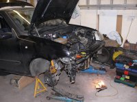
Heres just a side shot with the brakes back on:

P1010812.jpg

Heres the kind of clearance to expect from the tank and rear, the front is still touching a little bit :bang:

P1010814.jpg

P1010815.jpg

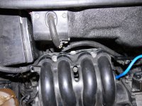
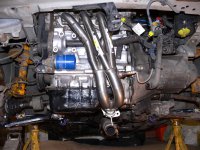
And finally heres a shot of the manifold fitted (y) I may be able to fit the current exhaust in temp, so i can drive it to a fitters, or do it properly myself.

You can also see the powerflex bushes and the larger superflex ARM mounts and bushes :D

P1010816.jpg


@Dave, i could move the MAF, but it already looks a mess with the charcoal cannister, I'd rather just ectend connectors if possible.

Cheers chris for all those pics, they were usefull :)

Thats it for tonight!

Kristian
 
Last edited:
Its all gone mighty quiet in here :) Maybe I better get my arse into gear and do someting more interseting than what I am :)

Had very little time recently, and this is an update of what I've done since I last posted (all 3 hours worth today lol)

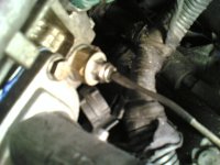
Here is the temperature adapter I bought, it converts the 1/8 NPT temperature sender to another thread.

I measured the plug I had next to the thermostat, and luckily got it right. It's a 1/8 npt to 5/8 unf thread. This allows me to measure the coolant temperature in the head, next to the thermostat. £10 from demon tweaks but seemed more elegant and reliable that tapping the thermostat.
21042007(001).jpg


I have also fitted a cutom fuel pipe length as the moulded fiat one got in the way of the intake. It's stainless wrapped to prevent wear and tear.


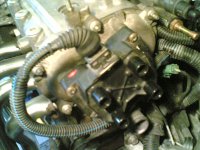
To rewire the loom I popped to a local scrappy and got a full bravo 1.4 engine loom for £10 to strip for wire. It also had the relevant connector I needed for the coil pack.

I rewired the coil leads to fit the newer style coil, splicing two together. The older coils run two leads (4 wires), this newer coil runs on one connector, 3 wires.
21042007(002).jpg

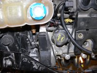
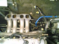
I also extended the TPS and another sensor wire (what is it, is not the map or tps, so its..?). It involved 7 wires, 14 solder joints and wasn't the quickest job, all heat shrunk and long enough now. Only one more sensor to extend.

21042007(004).jpg

I also blocked the breather vacuum inlet and presure regulator vent on the TB.


Will have a bit more time to do some tommorrow evening, so hopefully get all the soldering done. Then the TB and inlet can go on properly.


hope your all still enjoying the progress....seeing Emma's runnign really make me want to get this done ASAP!


Kristian
 
Last edited:
Its all gone mighty quiet in here :) Maybe I better get my arse into gear and do someting more interseting than what I am :)

Had very little time recently, and this is an update of what I've done since I last posted (all 3 hours worth today lol)


Kristian

Also soldering this week, god its boring. Trouble is you have to get it right ...:) Keep up the good work.
 
Just out of concern - do I see right from the earlier picts that you have the spark plugs out and nothing in the holes to protect small things dropping out of your hand into the engine? (I might be wrong though, it's not clear from the pics) Don't have to tell you what trouble you would be in then ;)

Cheers,

Woj
 
Back
Top