Technical Carburettor problems?

Currently reading:
Technical Carburettor problems?

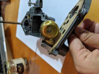
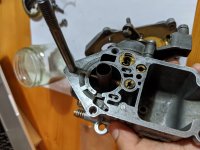
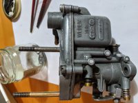
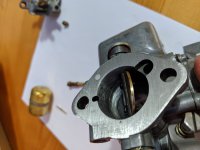
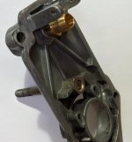
The easiest way to measure the float level is to use a drill (or a tube or rod) of the correct dimension, which is 7mm when the carb top is held in a VERTICAL position--don't worry too much about the '15mm' dimension. Did you give the float a shake and check that there is no fuel inside it? If there is, that will affect the running ofthe engine--it needs to be replaced (cannot be repaired).
Look on your dynamo-belt pulley--there might be a small 'flat' on the outer side of the casting, which will line up with the timing mark on the oil-filter cover (which will only fit onto the pulley on one position). There will be a corresponding mark (small raised cast 'line') on the timing-chain cover. If you have 'points' ignition you can statically check the timing with a small timing light (bulb with 2 wires and small 'croc-clips' will suffice).The correct static timing for the 500 engine is 10 degress before top dead centre (BTDC), or the mark on the pulley/filter when it is 13mm before the mark on the timing-chain cover (the engine turns clock-wise, looking from the rear of the car). Clip one of the wires from the bulb to the distributor side of the coil and the other wire to the body (earth). Ensure rotor arm is aligned with no '1' on the distributor cap. Remove ignition lead from coil or distributor cap (safety item--so that the car doesn't start on you). Turn engine to set timing marks on pulley/t-c cover, turn ignition on. Turn distributor CLOCKWISE until light is out---then turn distributor ANTI-CLOCKWISE until light just comes on.tighten distributor clamp nut, refit ignition lead.
 
1) Re-check the contact breaker points. If they are used, a pip can form on one face resulting in the gap not being set correctly.
Slide a piece of clean white paper/card between the points contact faces to check for any contamination (any oil on the feeler gauges gets transferred when adjusting the gap). Clean the contact faces with Brake cleaner spray or similar.
____________________________

Checking the ignition timing without a timing light/gun.:-

Remove the distributor cap, rotate the engine, with the ignition turned on, to where the timing mark on the crank pulley is approx. 30mm to the left (anti-clockwise) of the fixed timing mark on the timing cover.
Connect a test light between the wire going to the contact breaker points and a good earth point. (With the points closed, the light will be off, when the points open, the light will go on).
Now turn the crank and see when the light comes on, this is your static ignition timing setting. The light should come on (i.e. the points should just open) when the crank timing mark is approx. 13mm to the left of the fixed timing mark. If this is not correct, loosen and turn the distributor until it is o.k.
Timing the ignition statically is quite sufficient for normal use.

Alternatively, the timing marks can be set 13mm apart, then loosen and rotate the distributor until the light comes on (i.e the points have just opened), then nip up the distributor clamp.

If you don't have a test light, you can either watch for the small spark that occurs between the contact faces of the points as they open, or watch carefully to see when the points just start to open. (some people place a sheet of paper between the contact breaker points, when you can easily pull it out, the points have just separated).

When you think you have it adjusted correctly, rotate the engine forward one full turn to double-check your adjustment - don't turn the engine backwards if you miss the point where the points open, there'll be some backlash in the distributor drive which can give an inaccurate reading.

____________________________

You changed the distributor cap and rotor arm? - are they exactly the same as what were originally fitted?, if not, try refitting the originals in case there is a difference.
_______________________________

Whenever you're faced with a problem that could be either ignition or carb., it's usually best/easier to rule out any problem with the ignition system first, then tackle the carb.
_____________________________

Re:- your carb.
In the Downloads section (blue band at the top of this page) there is a section on the 500 (Classic) - if you select this, you can download (for free) a copy of the factory Fiat workshop manual.
In this, the Weber 26.IMB is covered, along with the other carb models.
For your carb, float adjustment is covered on p.39 (they show 7 and 15mm, - your 9mm will result in the carb fuel level being too low), choke unit is on p.41 and the carb differences on p.40.
__________________________

Some other things to consider are :-

Failing condenser, as several others have already mentioned (condensers seem to give a lot of trouble on the 500, especially modern aftermarket ones). If in doubt, fit a new one. (you mentioned you have one but not fitted yet?).

Fuel blockage? Did you clean the fuel mesh-type filter in the carb? It's under the large brass nut (iirc 19mm?) in the carb top cover adjacent to the fuel inlet pipe.

Failing fuel pump? To check output, disconnect the fuel pipe from the carb, place open end in as container (glass jar) and spin the engine over with the ignition off, to see if you have adequate output from the pump.
___________________________

In summary:-

Check points gap and clean.
Check/adjust ignition timing.
Fix choke as per the workshop manual.
Set float upper/lower levels as per the w/shop manual.
Check fuel flow rate and that filters are clear. There are 3, mesh screens in fuel tank pick-up pipe, fuel pump (under the top cover) and at the carb fuel inlet.
Fit new condenser (1st or last, your choice).

Al.
 
Several pictures of the carb, while assembling it back together.

There is no mesh fuel filter on mine. No place to put it:)

also the cap on the spring of the "choke" is different from most pictures I have seen.

The Venturi tube seem to be made of plastic ( is this possible ? )

I posted a picture with all the number of the metered holes. Might be useful for some one else.

When close the venturi flap partially closes the pinhole at the bottom. Should it partially close or should it be clear from obstruction?
 

Attachments

  • IMG_20200831_203535.jpg
    IMG_20200831_203535.jpg
    870.9 KB · Views: 47
  • IMG_20200831_204117.jpg
    IMG_20200831_204117.jpg
    850.2 KB · Views: 46
  • IMG_20200831_194033.jpg
    IMG_20200831_194033.jpg
    612.4 KB · Views: 45
  • IMG_20200831_194056.jpg
    IMG_20200831_194056.jpg
    630 KB · Views: 54
  • IMG_20200831_195828.jpg
    IMG_20200831_195828.jpg
    907.1 KB · Views: 86
  • IMG_20200831_195644.jpg
    IMG_20200831_195644.jpg
    637.8 KB · Views: 69
  • IMG_20200831_193753.jpg
    IMG_20200831_193753.jpg
    970.7 KB · Views: 44
  • IMG_20200831_204521.jpg
    IMG_20200831_204521.jpg
    871.3 KB · Views: 84
  • IMG_20200831_195636.jpg
    IMG_20200831_195636.jpg
    706.9 KB · Views: 74
  • IMG_20200831_194112.jpg
    IMG_20200831_194112.jpg
    972.7 KB · Views: 66
  • IMG_20200831_194038.jpg
    IMG_20200831_194038.jpg
    577 KB · Views: 56
  • IMG_20200831_204533.jpg
    IMG_20200831_204533.jpg
    731.8 KB · Views: 71
Never heard of or seen a plastic Venturi. The lack of a fuel filter on the inlet means that is from one of the cheap repro carbs but the body does look More original. Could it be made up from bits & bobs. The brass slider on the choke should be easy to remove and clean and with the emulsion tube I find that a small screwdriver will fit nicely down the middle and with a bit of a wiggle the bit will ease out allowing you to clean down there. Other parts look pretty standard.
 
toshi - I am not sure it is plastic. But it is very light. It could be tin but it does not fill cold like all metal parts. The Carb does not feel like it is new, it has all sorts of dents and scratchs all over.

I just assembled everything back together. I did not know I could remove the emulsion tube out. So I did not force it out.

I did level the bottom now. It was warped before.

F123C

Latter this week i will do

1 - Put the carb back in the engine
1.1 - Fix choke as per the workshop manual. : done :)
1.2 - Set float upper/lower levels as per the w/shop manual. Done:)

2- Check points gap and clean.


3 - Check fuel flow rate and that filters are clear. There are 3, mesh screens in fuel tank pick-up pipe, fuel pump (under the top cover) and at the carb fuel inlet.

I only have one at the exit of the fuel tank. It is new and is clear.

4 - Fit new condenser (1st or last, your choice).

5 - Check/adjust ignition timing.

Still a little be scared of messing with this . Will read everything you posted and try to find video or something to make sure I do not mess the car :)
 
As far as I am aware there were some carbs made under licence in Spain and were of a reasonable standard then there were some pretty nasty ones made in China. I had to check so looked at my spares in my garage. On the Italian carbs they have Bologna on the top cover and Italy on the main body to the left of the choke mechanism.
 
Put the carb back. Still had problems with accelerating.

Then I changed points and the condenser. And now it running good!

Not sure if it was the points or the condenser but there was a central pit in the points, I think those only happen when the condenser is failing!

I would like to rest the old condenser but do not know how.

I could not change the parts of the points, the new part was already broken on arrival, no contact part (Chinese part?).

The carb still has a leak issue on the top joint. I will post a slow motion video of the fuel escaping thru the joint.

Thank you all for all your help! I would never have thought it was a electrical issue.
 
Apology to 'the hobbler'

Sorry Tom,

I was busy typing my post #22 (overlong as is my norm!) which included looking up some info in the Fiat workshop manual for the OP and missed your post #21 describing the procedure for adjusting the ignition timing statically - I didn't mean to duplicate what you had already written.

Regards,

Al.
 
Several pictures of the carb, while assembling it back together.
-----------------------------------
-----------------------------
----------------------

When close the venturi flap partially closes the pinhole at the bottom. Should it partially close or should it be clear from obstruction?

Great job with the pics, very clear. (y)

The venturi flap is usually referred to a 'butterfly valve' or 'throttle plate' in workshop manuals written in English, might help avoid any confusion.

I wasn't aware that you had dismantled the carb this much.... my experience is that people can get themselves into great difficulty when they remove this throttle plate. And into even more difficulty if they bore out worn spindle holes in the carb body to fit bushes but bore the holes off-centre....

Anyway, looking at pic 10 of 12 you've posted, it seems to me that the throttle plate maybe isn't centralised? - with the idle speed screw on the throttle linkage backed off fully, the throttle plate should close off the carb. bore completely. As things stand, there seems to be a slight gap on the right side but the throttle plate is touching the carb bore on the left side. The pinhole that you mention is the where the fuel at idle comes into the carb - it doesn't have to be completely uncovered but it does have to be positioned so that the small amount of air that passes around the throttle plate at idle (i.e. when you turn in the idle speed adjusting screw, it opens the throttle plate very slightly) can cause a depression (vacuum) across the hole, thus drawing the fuel out.

That throttle plate (butterfly valve) can be fitted in 2 ways, one right, one wrong! There's a slight chamfer along 2 areas of the circumference to allow the plate to exactly match the carb bore when closed, it's important it's fitted correct way around and then centralised. To centralise it, back off the idle speed adjustment screw fully, loosen the 2 screws holding the throttle plate, snap the throttle closed a couple of times to centralise the plate (hold the carb up to the light to ensure it's centralised i.e. that no light can be seen around the plate's circumference) then hold the throttle closed and tighten the 2 screws. These screws should have been coated when fitting with a fuel resistant thread locking compound and are usually 'peened over' to ensure they can't ever fall out.

(Iirc, the figure 78* on your throttle plate indicated the amount of chamfer on it's edges? or maybe it's the angle of the throttle plate when fully closed?)

In pic 8 of 12, the idle jet holder can be seen - it's the large brass slot-head screw with the rubber O ring that's partially unscrewed. Some of your other pics show this removed and alongside other carb jets etc. You don't appear to have separated the idle jet from this idle jet holder - the idle jet part (it has 45 on it) just pulls out of the idle jet holder (you might have to carefully use 2 pairs of pliers). It's important that the recess inside the idle jet holder is cleaned along with the idle jet. The idle jet has a large cross drilling and a tiny hole in it's end - this is the metered part i.e. 0.45mm. Cleaning of this jet can be done with the carb on the engine, even at the side of the road - unscrew, separate into it's 2 parts, blow through the idle jet part, hold it up to the light to check that the tiny hole is clear, then reassemble and refit to the carb.

Al.
 
Put the carb back. Still had problems with accelerating.

Then I changed points and the condenser. And now it running good!

Not sure if it was the points or the condenser but there was a central pit in the points, I think those only happen when the condenser is failing!

I would like to rest the old condenser but do not know how.

I could not change the parts of the points, the new part was already broken on arrival, no contact part (Chinese part?).

The carb still has a leak issue on the top joint. I will post a slow motion video of the fuel escaping thru the joint.

Thank you all for all your help! I would never have thought it was a electrical issue.

It's not unusual for a 'pip' to form on one of the c/b points faces and a corresponding 'pit' to form in the other face - it's due to material transference caused by the small electrical sparking that occurs in normal use, even with a condenser that is functioning normally. In fact, in used to be normal practice to file down this little pip before resetting the points gap and then the ignition timing. In the good old days :) , garages used to sell 'points files' for this purpose - I haven't seen these for sale in many years, but I suppose you could use a flat 'needle' file or maybe a diamond-coated file, possibly even a diamond-coated nail file might work. The material for the points contact faces is usually tungsten, a very tough metal. Some people just swipe some abrasive paper between the contacts to clean them up - ideally you should use 'glass-paper' not silicone carbide paper, then just clean them afterwards with brake cleaner or similar. Make sure the contact faces are meeting squarely when closed for long service life. Apply a tiny amount of grease to the points operating cam to minimise wear on the points actuating heel.

There is no easy way of checking out a condenser at home (requires specialist equipment) so the usual advice is just fit a new one if in doubt.

Re:- the carb fuel leak - very weird, you seem to have cleaned and trued all the carb joint faces and fitted a new float valve, plus set the float height. The only thing I can think of that might cause the fuel leakage (I watched your videos) is if the fuel height is creeping up over the 45 secs and yet your engine doesn't sound like it's flooding.....

In one of your carb pics, I noticed a dent in the carb float - this would make me very suspicious. As Tom (the hobbler) has already recommended, best check out the float, not just for any fuel getting into it (shake it to test)which will cause flooding of the carb but also check it isn't binding anywhere in it's range of movement.

At least you're making progress (y)

Al.
 
It is not uncommon for the carb top cover to warp where people have applied too much pressure to the four mounting screws often when the gasket has started to disintegrate. I have straightedges out a few successfully.
 
It is not uncommon for the carb top cover to warp where people have applied too much pressure to the four mounting screws often when the gasket has started to disintegrate. I have straightedges out a few successfully.

Should I apply pressure using a vice with both top and bottom together? Or is there some other technic that is less risky?

I don't know if you noticed on the pictures but I added a nut to the second screw because I had no thread on top part. It has enough clearance so it is not hitting anything on the bottom part. But it could be blocking any flow inside the carb? Any recommendations ?
 

Attachments

  • IMG_20200831_194033.jpg
    IMG_20200831_194033.jpg
    612.4 KB · Views: 57
Should I apply pressure using a vice with both top and bottom together? Or is there some other technic that is less risky?

I don't know if you noticed on the pictures but I added a nut to the second screw because I had no thread on top part. It has enough clearance so it is not hitting anything on the bottom part. But it could be blocking any flow inside the carb? Any recommendations ?

I am not sure what you mean by this nut and second screw thing. Looked at the pictures but not spotted anything.
So with the carb warped top I would remove the centre stud, assemble the top onto the carb body and press them together in a vice. Hold it up to the light and see if you can see light through the gap. If you do see light as the top may have a little spring in it put it back together again with 4 equal washers where the gasket would sit & held in by the screws. Re-apply pressure in the vice and keep testing the gap until it is even. It can be advantageous to reverse the bow just a tiny amount so that when you refit the top it pulls straight with a new gasket by the 4 screws.
 
I added this nut that you can see a close up picture. It was not there but i needed to add it or else the screw would drop out.
 

Attachments

  • Screenshot 2020-09-02 at 15.28.28.jpg
    Screenshot 2020-09-02 at 15.28.28.jpg
    67.4 KB · Views: 84
May I suggest that you remove the nut and use something like "JP Weld" to secure the stud in place.
I have just looked at my 28IMB and the top of my carb looks different to yours in that on the top of my carb the "Weber" is shown in the "EW" casting and the words "Carbureture WEBER made in Italy"---your carb top has a somewhat crude "W" and no "made in Italy".I would suggest that your carb is NOT a genuine Weber carb---this fact may be contributing to your problems.
I would suggest that you have a wander through E-bay and see if you can find a good 2nd hand GENUINE IMB carb. Some of the Italian e-bay sites are usually a good place to look---try "[email protected](also on:--- www.autoricambilineaverde.it)
 
I tested the car yesterday.

- Started with almost no choke
- Very stable idle. No fluctuation
- Good acceleration

Quirks:
- Using choke at any moment ( cold or warm ) mad it almost die
- Turning the accelerator screw did not accelerate the idle
- Idle mixture had almost no effect on the idle. Had to fully close it to make the idle run rough.

Next steps:
- take the carb out
- Re adjust butterfly
- Take the screw ou and put JB weld in place
- Flatten the top of the Carb to eliminate the GAP or put a additional gasket
- Put the 112 injector back ( now it is 120 )
- Try to determine the origin of my Carb


Overall, great progress because of all your help!
 
I hope you mean just a new gasket and not additional one , ie fitting two. I have got quite a few Spare Weber 26IMB carbs here plus bits if anything goes wrong.
 
I hope you mean just a new gasket and not additional one , ie fitting two. I have got quite a few Spare Weber 26IMB carbs here plus bits if anything goes wrong.

To be honest, if i cannot get it straight either by using a vice on sanding it down I really meant putting old gasket plus new one on top of each other...is this really a dumb strategy? :)
 
To be honest, if i cannot get it straight either by using a vice on sanding it down I really meant putting old gasket plus new one on top of each other...is this really a dumb strategy? :)

Don’t be so hard on yourself, I would say just misguided :)
Two gaskets is more likely to increase the bow in the top cover if the original is over compressed in the area of the screws. Just make sure that top cover is flat or a very slight bow in the opposite direction and all will be OK with one new gasket. Greatest respect to guys who are prepared to give things a go themselves :slayer:
 
Back
Top