Technical Gearbox Rebuild 2nd Gear Synchro Unit

Currently reading:
Technical Gearbox Rebuild 2nd Gear Synchro Unit

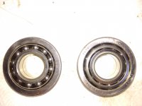
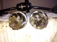
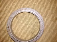
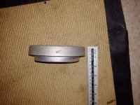
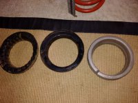
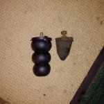
I have one of the "Motomax" C/V kits sitting in my workshop (to go on my car when I fit the '5 speed' gear-box', so I dug it out and inspected it. The rounded end of the nut (the nyloc end) fits snugly into the inside of the part of the joint that fits onto the stub-axle shaft. If the nut was fitted the 'correct' way round there would be very little of the nut in contact with the coupling--only the corners of the 'hex' in fact.
There are 2 ways round this problem--both involve a machine shop (or the clever use of a lathe)--(1) have the nut/coupling contact area machined flat or, (2) have a special little washer made that will fit snugly into the coupling and also allow you to fit the nut the correct way round. (y):)

I'd imagine the material in the joint is quite hard so might have to be ground.
(I'm not familiar with the capabilities of lathe cutting tools).

Your idea of some sort of special washer sounds quite workable. I used to work on trucks a long time ago, some used a shaped washer iirc between the brake drum and wheel fitted over each wheel stud to engage with the recess on the rear face of each stud hole. A bit like the tapered/coned wheel nut used on the outside of the wheel. I mention this because 16 or 18mm is small stuff on a truck but big on a car.(I'm just guessing that the thread is about this size!). Maybe you could obtain some of these shaped seating washers or some old truck wheel nuts and cut off the taper/cone/dome part, clean out the thread and use as special washers under the nyloc nuts in your new CV joints. Of course if you have access to a lathe you would probably just turn some suitable washers in less time.

I don't suppose there is sufficient room and thread length to fit a very thick/heavy washer under the nyloc nut if fitted in the normal/correct way.

Or you could maybe turn the seating part of the nyloc nuts to match the recess in the CV joint. (the nuts are probably softer than the CV joint).

P.S. Any other colour options available? :D

AL>
 
I have managed to get a small job done on my 126 and BIS gearboxes today, that of removing the crosshead screws holding the rear pinion shaft bearing retainer (y)(y)(y) If you have a screwdriver big enough and the grip of a gorilla you may just get them to move :mad::mad: Me, I just resorted to a bit of brute force and an impact driver :devil::devil: they still took some hammering to come loose!!!!
The reason behind all this parts removal is that I want to have the best set for my rebuild and am checking the wear and tear on all bearings. Although the gearboxes differ in age and application there have been a few details that differ between each box. The BIS box carries a serial number on the casing, the 126 does not and the later box (BIS) has a modified bearing for the rear of the pinion shaft :confused::confused: (see pic) it's obvious that the later polish made item has a retainer to hold the ball bearings in place - I found this out after having the forward race of the 126 pair fall apart upon removal :eek::eek: that caused a few minutes of cursing before I found all the balls and reassembled it :mad::mad: Another weird note was the difference between the pinion gear head - apart from the actual number of gear teeth (BIS-9) (126-8) both stampings quoted the same gear ratio of 8/39 ??? Some much needed info has been found to be difficult to obtain however, the individual measurement +/- of a nominal 75mm between the centre line of the differential to the rear face of the pinion found on the threaded end of the pinion shaft is almost invisible and will need a magnifying glass to read :mad::mad: but given the info above from Toshi I may not need the exact figures - fingers crossed!!(y)

Ian.
 

Attachments

  • IMG_20171104_152003.jpg
    IMG_20171104_152003.jpg
    1.6 MB · Views: 23
  • IMG_20171104_152149.jpg
    IMG_20171104_152149.jpg
    1.9 MB · Views: 25
With a bit of faffing around I eventually got my dti set to check pinion to crown wheel backlash today (y)(y) With the gearbox assembled al la Toshi, I was pleased to note that the gear meshing between the pinion and crown wheel was spot on with full tooth contact, so using the BIS shim set has done the job :D
The backlash was non-existent however (n)(n) The screw adjusters set into the bearing retainer would not turn with large pin nosed pliers either, so one demerit point to Mr Haynes awarded there :mad::mad: The turning of the adjusters had to be achieved with a broad punch and light hammer (y)
It took awhile to adjust both sides and check after each movement, but I eventually got there. The turning torque of the Diff bearings is the next job, but should be straight forward now that the gearbox is in neutral, the gear drag is considerable when assessing how well the drive shafts turn and my shed is very cold at the moment, now where did I put that heater!!! :devil:
Ian.
 

Attachments

  • IMG_20171112_133356.jpg
    IMG_20171112_133356.jpg
    2.1 MB · Views: 23
I managed to get the differential bearing turning torque done today (y) It's all a bit Heath Robinson to me :rolleyes: but there is a slight difference between the method in the Haynes 500 and 126 books. I don't have access to the adjusting tool used on the 126 gearbox so the 'old' method will have to do :D
After gaffer taping (my favourite tool) a suitable length of copper tubing to the end of the drive shaft and collecting a 1lb bag of 3/4in gravel it was a simple enough job and the bearings only needed a tweak - next get it all back into the car!!!!:devil:

Ian.
 

Attachments

  • thumbnail_IMG_20171113_140933.jpg
    thumbnail_IMG_20171113_140933.jpg
    27 KB · Views: 23
Before the now finished gearbox goes back on I resolved to sort the rear suspension height (y) some nice progressive springs of 185mm had already been obtained. I took a quick look at Mr Haynes to get it all into my head and set to, But, I noticed something different on the car - between the top spring seat and the spring itself there was an additional alloy spacer??:eek::eek: I removed the spring assembly and noted that the alloy spacer is marked 127,128,131 and Ritmo ?? When measured the spacer was 20mm. I then checked the original spring and that was 195mm so together they gave a lowering value of 6mm from the original height of 221mm :confused::confused::confused: Question, why on earth would you fit a lower spring and then fit an addition 20mm spacer??:confused: The only reason I can think of is to accommodate the larger wheel/tyre size (165/60x12) :(:( So, until I can see how the car settles with the engine and gearbox back in the original springs have gone back on sans spacers, only then will I know if the new springs will fit at 185mm (y) I now have the rear suspension lowered to 195mm (down 26mm) which should help stop the car suspension behaving badly in corners :slayer::slayer: see pics (sorry for the quality)
Ian.
 

Attachments

  • IMG_20171126_133025.jpg
    IMG_20171126_133025.jpg
    1.8 MB · Views: 18
  • IMG_20171126_132903.jpg
    IMG_20171126_132903.jpg
    1.6 MB · Views: 21
  • IMG_20171126_132535.jpg
    IMG_20171126_132535.jpg
    3.7 MB · Views: 19
  • IMG_20171126_132751.jpg
    IMG_20171126_132751.jpg
    2.3 MB · Views: 19
  • IMG_20171126_132458.jpg
    IMG_20171126_132458.jpg
    2.2 MB · Views: 17
Greetings, Now ready to refit the gearbox as the engine is on the way, but have wanted to fit a 126 type 'gearbox torsion plate' (y)(y)
Does anyone have pictures of where the forward bolt comes through the floor of a 500 ???? I don't want to just have at the underside with a drill without knowing where it is going to come out :eek::eek: any help appreciated, thanks.

Ian.
 
The bolt doesn’t go through the floor it screws into a threaded bush which if memory serves is 20-25mm from the rear edge of the floor.

Ralph
 
Greetings, Now ready to refit the gearbox as the engine is on the way, but have wanted to fit a 126 type 'gearbox torsion plate' (y)(y)

Does anyone have pictures of where the forward bolt comes through the floor of a 500 ???? I don't want to just have at the underside with a drill without knowing where it is going to come out :eek::eek: any help appreciated, thanks.


Ian.


Still have to fit mine but I think Andrew Harvey has one fitted. I believe the front bolt comes through the floor inside the tunnel and can be accessed via the panel next to the heater control lever
 
I was guided by Andrew's fitting and used the stabiliser as a template after loosely bolting to the gearbox cradle. I just used a nut and bolt and the hole I drilled was well clear of anything important and I think it aligned with the folded over flange of the rear floor.
I came to the conclusion that it's designed to work with the later type of engine mounting as I still get the occasional clunk with the bigger, heavier engine.
 
Greetings All, just going back to my suspension concerns and the ride height in particular. I have previously noted that my rear tyres will contact the rear area of the wheel arch just before the swing arm hits the bump stop :mad::mad:
So that I may complete the reassembly of gearbox and engine into the car without knowing exactly how it will all settle I have changed my bump stops in the event that wheel and arch come into contact before any road work is done.
The standard 500 rubber stop is a solid cone and measures 58mm in length, as I need some greater distance after bump contact I looked around and found that the 126 item measures 92mm in length (see pic) it is also hollow (y)(y)
So a trial fit is taking place using the 126 item to assist in preventing wheel and arch contact during road work. I'll follow this up once everything is back together.

Ian.
 

Attachments

  • IMG_20180111_141331.jpg
    IMG_20180111_141331.jpg
    1.7 MB · Views: 24
  • IMG_20180111_141558.jpg
    IMG_20180111_141558.jpg
    1.7 MB · Views: 18
I was guided by Andrew's fitting and used the stabiliser as a template after loosely bolting to the gearbox cradle. I just used a nut and bolt and the hole I drilled was well clear of anything important and I think it aligned with the folded over flange of the rear floor.
I came to the conclusion that it's designed to work with the later type of engine mounting as I still get the occasional clunk with the bigger, heavier engine.

So Peter, did you have the bolt just coming up through the floor under the carpet or was it inside the tunnel, I just need to be sure (y)(y)(y)

Ian.
 
Back
Top