Hi
In your main photo, the bit at the top is the B001 under-dash junction unit/fuses/relays. Immediately behind it is the M001 body control module, which joins directly to it by a multiway connector pair (Connectors X and Y)
M001 pokes down below B001, and along the bottom edge from left to right is Connector C, The OBD socket, Then Connector A (The 52 pin blue one you refer to as the AV connector).
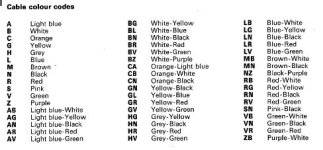
A search in eLearn using the code M001A will bring up the pin allocations table which for the used pins includes the wire colour codes and the cable cross sectional area. There are four near-identical tables depending on the exact vehicle. Annoyingly, the functions of the wires aren't listed, just their destination.
In my copy of eLearn Pin 13 isn't listed for any version, but other components using this INT line from F37 are coded L (Dark Blue). This line supplies a handful of different components.
Pin 17 is listed as RN (Red/Black)
Pin 46 is listed as RN (Red/Black)
Given the diagram of the connector, you may be able to identify Pin 1 and count along the pin numbers as an additional confirmation that you have the right pin.
I sometimes find that the training manual is in error, possibly because it was produced quite early in the vehicles life and maybe things hadn't been finalised for production ! eLearn is generally OK
Looking at the standard of workmanship, and given that you have intermittent connections, I would be inclined to re-make all these joints properly, e.g by using solder and heatshrink.


![bodyComputerAV_1[1].jpg](https://www.fiatforum.com/attachments/bodycomputerav_1-1-jpg.410052/ "bodyComputerAV_1[1].jpg")
![bodyComputerAV_2[1].jpg](https://www.fiatforum.com/attachments/bodycomputerav_2-1-jpg.410053/ "bodyComputerAV_2[1].jpg")
![bodyComputerAV_3[1].jpg](https://www.fiatforum.com/attachments/bodycomputerav_3-1-jpg.410054/ "bodyComputerAV_3[1].jpg")