So in effect it is totally separate? The ECU must have some form of cranking signal via 4 and 5 pins to trigger the fuel injectors when engine is running otherwise it would just keep pumping fuel all the time when ign. on.
If there is no Crank Position type sensor in the setup, then I would expect a connection to the distributor module.
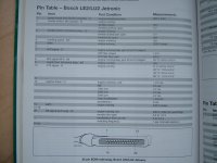
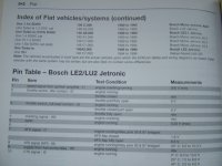
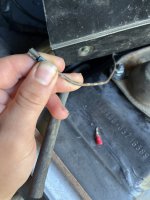
When cranking and good spark, can you find a pin from the ignition module on the distributor that gives a signal when engine turning over ? If so I would be tempted to run a wire to the ECU pin 4 via a very low amp fuse or something else to protect the ECU. According to that photo it is less than .25 volt, see if anything like that is coming from the distributor module.
That one wire you have just mentioned, can you get a reading from it when cranking, if so it may be the answer. It must not be battery voltage! If in doubt put a low fuse in circuit!


 But do you know how the ecu should be grounded? Or get +12v